Table of Contents
Connection Diagram
1a) SM2-MU – master for all devices
For power supply see Power Supply section.
All individual Taroms connected as slaves - data are read from each device.
1b) Multiple Tarom 6000-M on a single RS485 bus
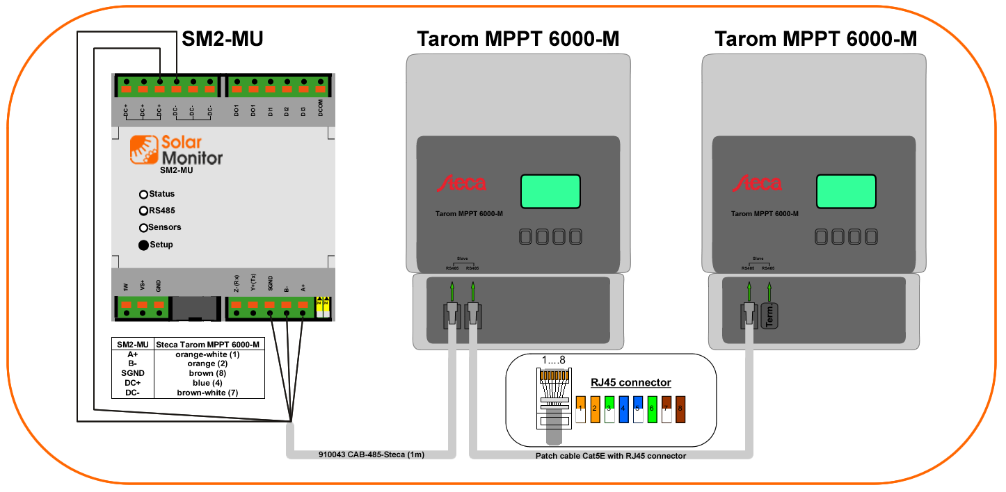
1a) and 1b) can be mixed
Both 1a) and 1b) can be used for each SM2-MU interface.
For short cables terminator is not necessary.
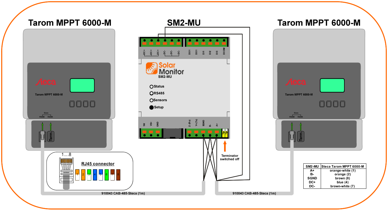
1c) SM2-MU can be placed in the middle of RS485 bus
For this case SM2-MU must be used with RS485 terminator switched off. Use yellow DIP switches to achieve this.
1d) Second SM2-MU serial interface can be used for additional Tarom device.

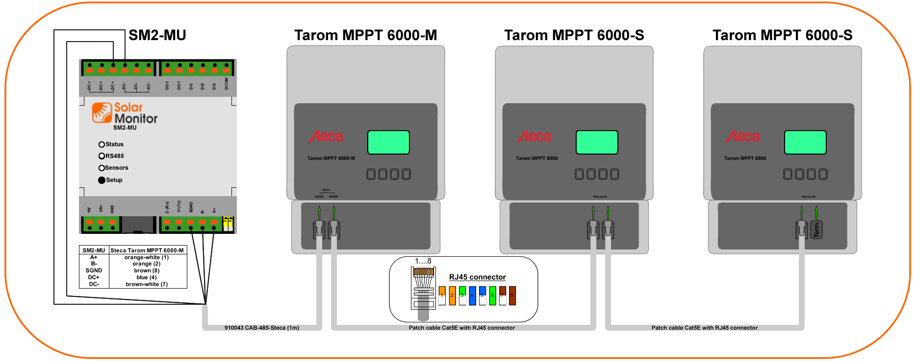
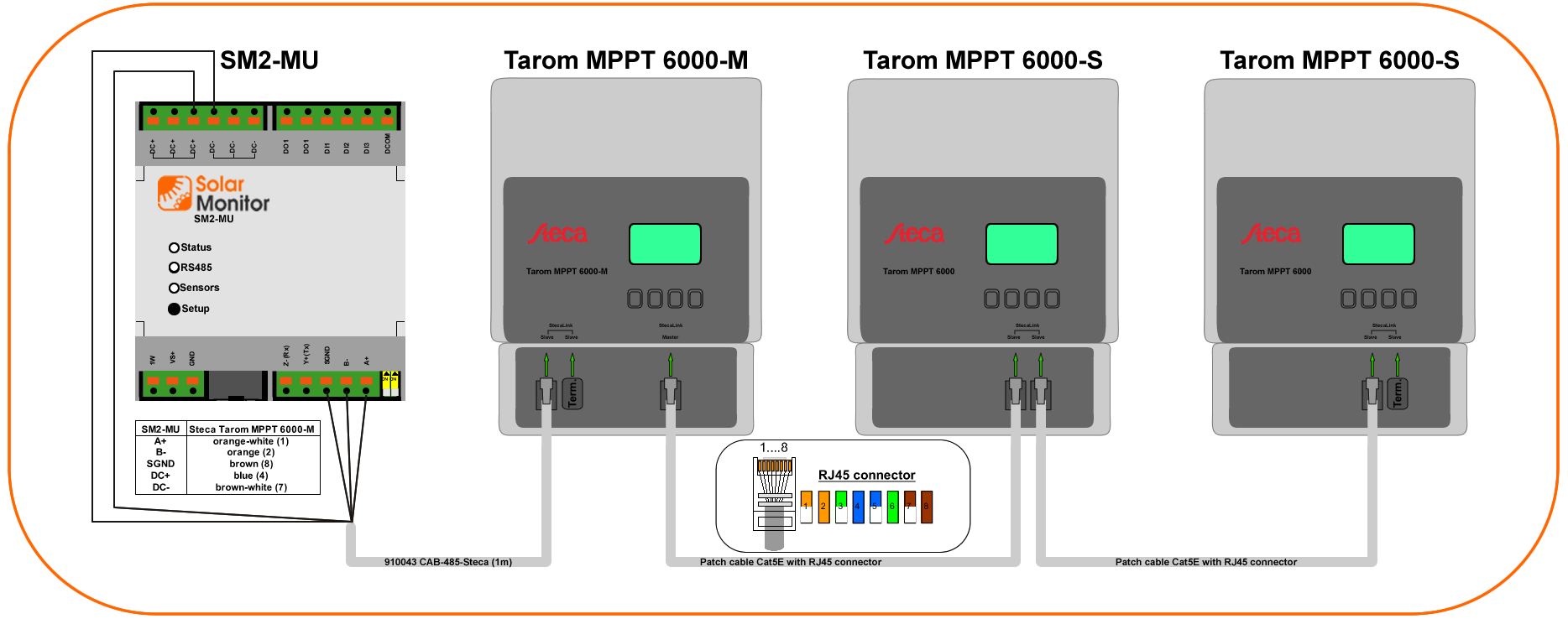
1e) Other bus cabling example using the MPPT 6000-M, MPPT 6000-S
MPPT 6000-S as slaves to MPPT 6000-M
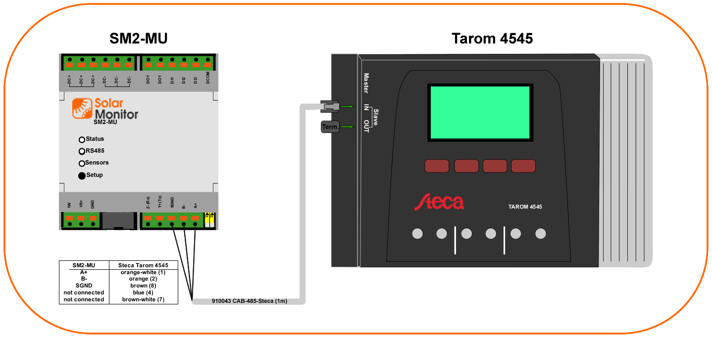
1f) SM2-MU + Tarom 4545
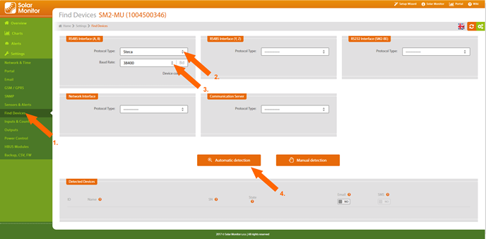
Detection