
en:sim:manual:jak_na_instalaci:fronius_layout
Toto je starší verze dokumentu!
Connection Diagram
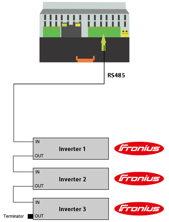
In a similar way, you can connect SM2 to connector OUT. Then terminator is connected to IN at the end of the bus (apply either when connecting to one inverter). In case of the involvement of multiple inverters, connect the inverters with straight cable.

RJ45 Connector Pinout
SM2 - Fronius IN
| PIN | Name |
|---|---|
| 1 | +12V |
| 2 | GND |
| 3 | Tx+ |
| 4 | Rx+ |
| 5 | Rx- |
| 6 | Tx- |
| 7 | GND |
| 8 | +12V |
SM2 - Fronius OUT
| PIN | Name |
|---|---|
| 1 | +12V |
| 2 | GND |
| 3 | Rx+ |
| 4 | Tx+ |
| 5 | Tx- |
| 6 | Rx- |
| 7 | GND |
| 8 | +12V |
Configuration Notes

en/sim/manual/jak_na_instalaci/fronius_layout.1411134866.txt.gz · Poslední úprava: 2014/09/19 15:54 autor: ondra