Solar Monitor User Guide
- Quick Setup
-
- Overview
- How to Install?
- Quick Start
- Factory Reset
- Web
-
- Extension Modules
This is an old revision of the document!
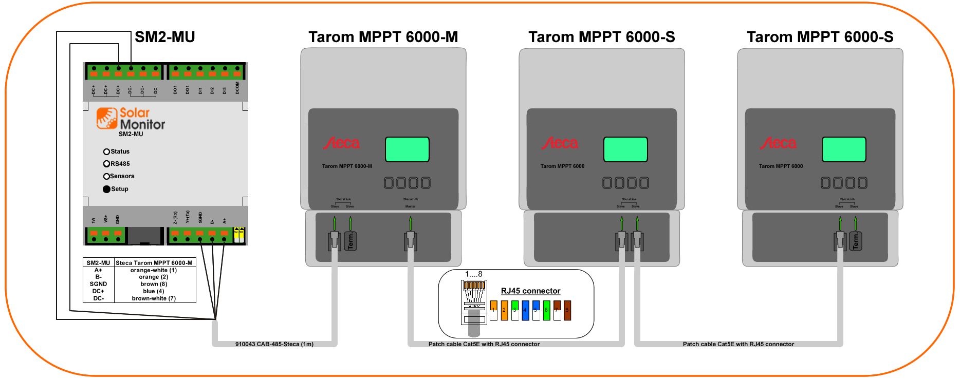
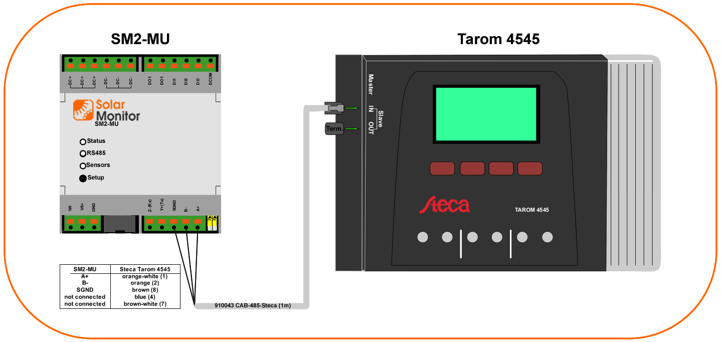
For power supply see Power Supply section.
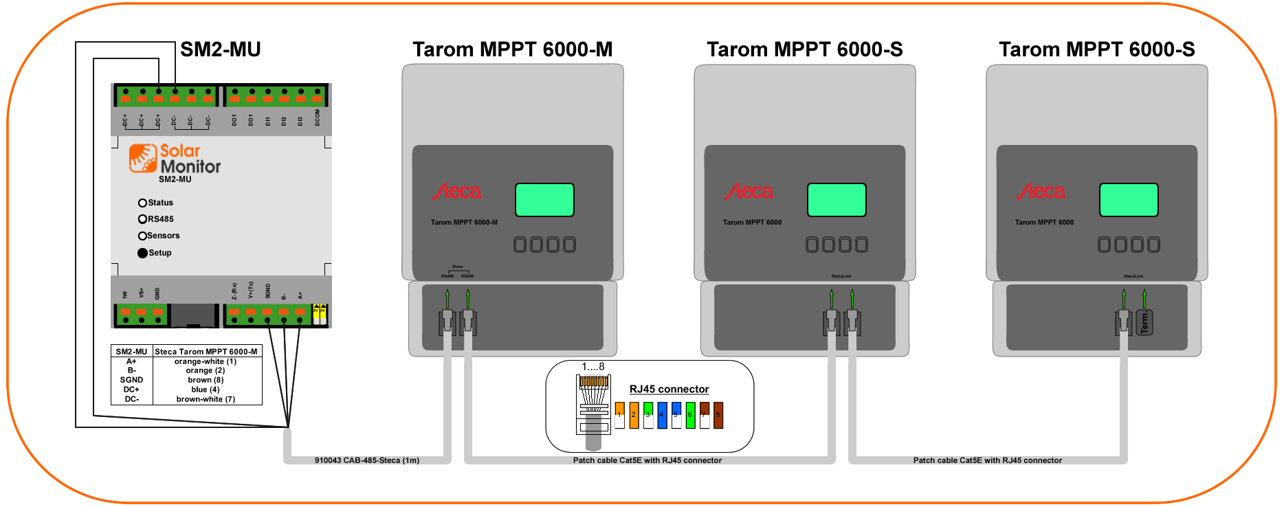
All individual Taroms connected as slaves - data are read from each device.
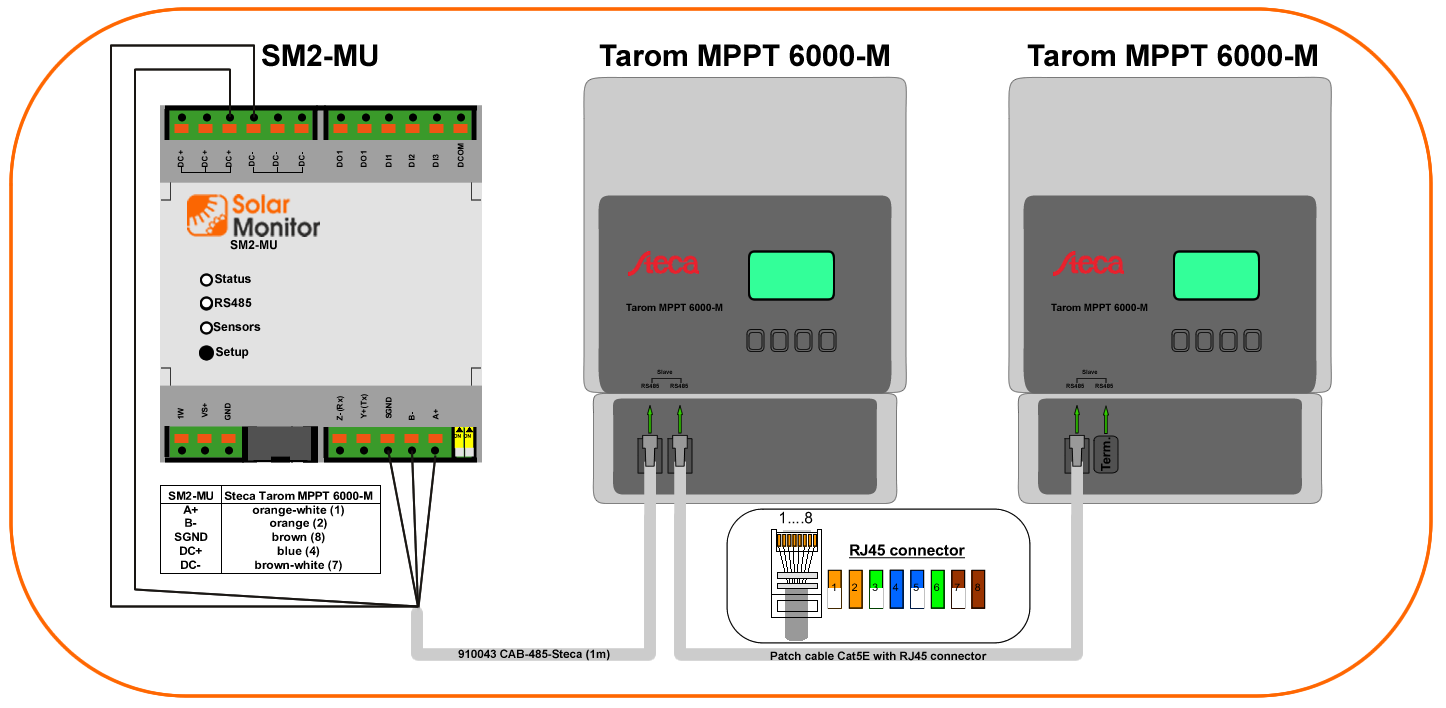
1a) and 1b) can be mixed
Both 1a) and 1b) can be used for each SM2-MU interface.
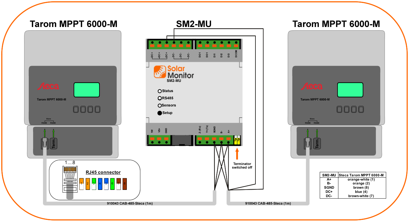
For short cables terminator is not necessary.
For this case SM2-MU must be used with RS485 terminator switched off. Use yellow DIP switches to achieve this.

MPPT 6000-S as slaves to MPPT 6000-M
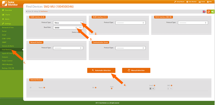
Detection