
SM2-DI
DI module increases the number of unit's digital inputs significantly and enables connecting other devices.
Connecting digital inputs
Module SM2-DI has 10 digital inputs. Digital inputs DI can be connected in the same way as inputs to SM2-MU. You can easily connect movement sensor, surge, optical barrier, door sensor and other devices that use contact output to indicate its status.
There are two ways of wiring.
The first one requires connecting terminal DC- to SM2-MU with relevant terminal DCOM at the module SM2-DI. One terminal DCOM goes with inputs DI1–DI5 and the second terminal with inputs DI6–DI10. In order to start the input, signal DC+ from SM2-MU unit has to be connected to relevant terminal of SM2-DI terminal.

For the second type of wiring, where inputs of SM2-DI module use external power supply (see the following picture), voltage has to be in the range of 8-80 V.

Start and configuration
When you have connected the modules and Solar Monitor unit has been connected to the power supply, green LED diode indicating status should glow. If it doesn't glow, check the wiring of SM2-MU and the module.
Open menu “Settings / Inputs & Counters” in your browser.
Select limit values for relevant connected inputs.
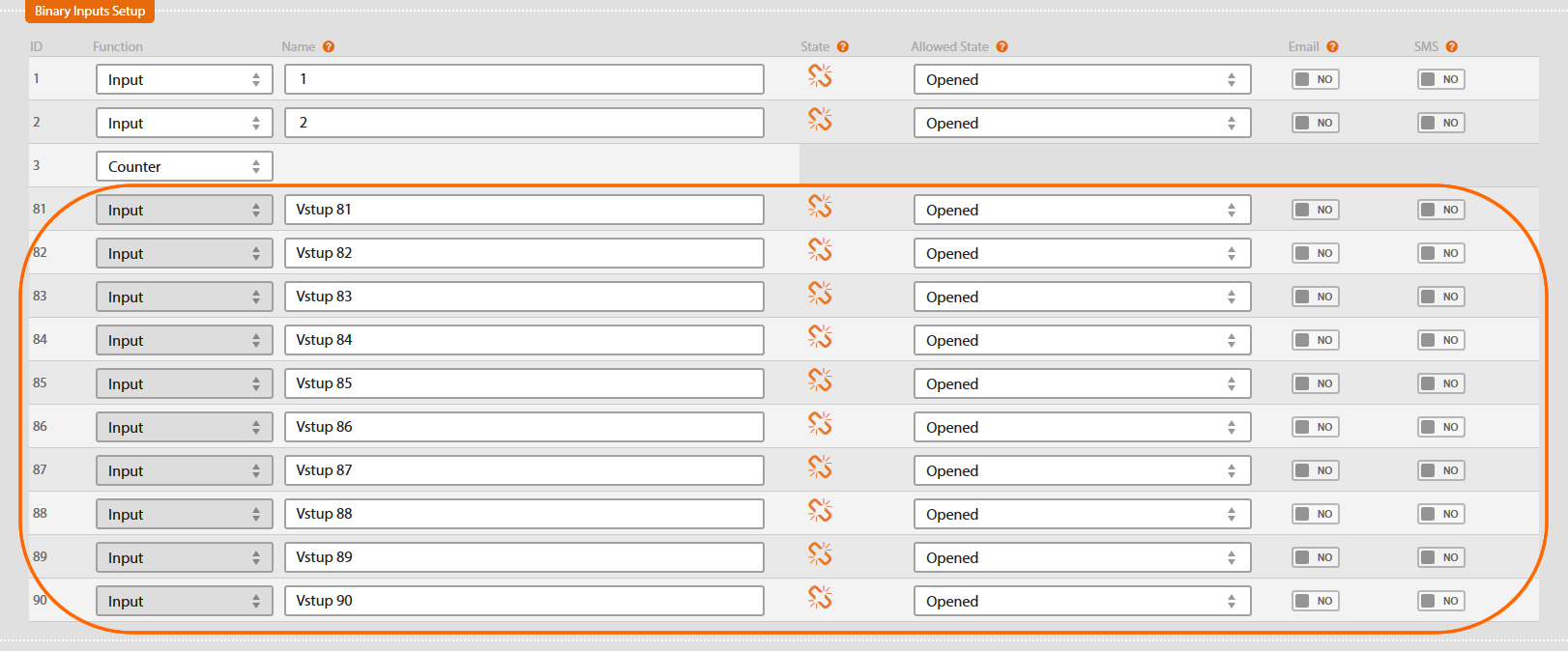
It is possible to choose the type of message (e-mail, SMS) that informs the user of changes in input values.
Technical specification
| Binary inputs | 2 x 5 inputs with standard Vcc and GND |
|---|---|
| Terminals | max diameter 1.5 mm? |
| Connectivity | HBUS |
| Dimensions | 35.6 x 89.7 x 62.2 mm |
| Installation | DIN rail |
| Power supply | 12 – 24 V DC, max 100 mA |
| Degree of protection | IP20 |
| Temperature range | -25 °C to +60 °C |
