
en:sim:manual:popis:parametry_zakladniho_modulu
Basic module parameters
| Max. number of devices1 | |
|---|---|
| SM2-MU Basic and SM2-MU Start | 1 device1 |
| SM2-MU 60 | 6 devices1 |
| SM2-MU 300 | 30 devices1 |
| SM2-MU 1000 | 100 devices1 |
| Supported devices1 | Ethernet or serial bus connected |
| Communication | Ethernet (TCP), up to 3 serial ports |
| Inverter protocols | AEG, Carlo Gavazzi, Danfoss, Delta, Diehl, Fronius, IBC Solar, Kaco, Kostal, Mastervolt, Morningstar, Omron, Pairan, Power‑One, Refusol, Riello UPS, Santerno, Satcon, Schneider‑Electric, Siemens, Siliken, SMA, Solarmax, Solutronic, Studer, Sungrow, Sunville, Sunways, Vacon, Xantrex |
| Meter protocols | ABB (REX521), Carlo Gavazzi (VMU-E/X), Fronius (Smart Meter), KMB (SMC-144, PA-144), Phoenix Contact (MA200/250), Schneider‑Electric (SEPAM, PM9), Yorix (GreenBonO), ZPA (IEC 62056-21) |
| Sensors | Dallas 1-wire bus |
| Interface | Screw terminals for 05 mm² - 15 mm² cores |
| Max. count | 10 sensors |
| Max. distance | 100 m, recommended max. cable length for daisy‑chained sensors with minimal trunk segments |
| Ethernet interface (LAN) | |
| Interface | RJ45 (100BASE-T) -100Mbit/s, compatible with networks 10/100/1000 Mbit/s, auto MDIX |
| Protocols | HTTP, SOAP, DNS, UDP Setup, Telnet, ARP, ICMP, SMTP, SNMP, Modbus |
| RS485 / RS422 / RS232 | |
| Interfaces | 2x RS485 or 1x RS4222 |
| piggy-back hardware options 3 | |
| 2x RS485 or 1x RS422 opto-isolated2 | |
| 1x RS485 + 1x RS232 | |
| 1x RS485 + 1x RS232 opto-isolated | |
| SM2-BE extension module | |
| 1x RS232 + 1x RS485 surge protected4 | |
| Speed | 300 .. 115.200 bps (software configurable)2, 5 |
| Termination | Yes, both for half and full duplex, configurable with jumpers |
| Inputs | opto-electronically isolated |
| 3x digital inputs (DI) | software configurable between dry contact or S0 pulse meter inputs (e.g. from electrometer) |
| Max. distance | 30 m (depends on cable) |
| Outputs | |
| 1x relay | 32 V, 3 A, protected with power fuse |
| Electrical parameters | |
| Power supply | 9-35 V DC, typ. 1.2 W @ 12V |
| DI1, DI2, DI3 | 8-80 V |
| 1 Wire | Interface provides 5 V power supply, max. 350 mA, protected with 500 mA power fuse. |
| RS485 | Protected against transient voltages above 6.8V and against high currents with 10Ω resistors. Additional surge protection can be achieved with SM2-BE (bus extension) module with gas discharge tubes: |
| Minimum DC Sparkover (100 V/s) 185 V | |
| Service life: | |
| 150 operations 8/20 μs 250 A, 1.2/50, 500 V (IEC61643-21) | |
| 20 operations 2/10 μs, 5 kV, 500 A | |
| 2 operations 8/20 μs, 1 kA | |
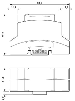
| Mechanical parameters | |
| Dimensions | 71.6 x 89.7 x 62.2 mm |
| Mounting | DIN rail |
| Screw terminals | 05 mm² - 15 mm² cable cores |
| Degree of protection | IP20 |
| Operating temperature | 0 .. +70 °C |
| LED diodes | Status, RS485, Sensors |
| Extension options | |
| Interface | HBUS (DIN rail, bottom pluggable, no external wires needed) |
| Extension modules | SM2-PC, SM2-AD, SM2-DI, SM2-GSM, SM2-BE |
1 … A device represents an inverter, stringbox, MPP tracker, battery monitor, meter or any other device which can be detected on any serial bus or via ethernet communication.
2 … Can be configured by software (web UI, XML).
3 … Piggy-back functionality replaces the “2x RS485 or 1x RS422” interface.
4 … SM2-BE is mutually exclusive to the SM2-GSM usage. 2x SM2-BE modules can be also used to extend the HBUS connection between SM2 modules.
5 … Communication speeds are available according to selected device communication protocols.
en/sim/manual/popis/parametry_zakladniho_modulu.txt · Poslední úprava: 2017/08/10 09:56 autor: ondra