Solar Monitor User Guide
- Quick Setup
-
- Overview
- How to Install?
- Quick Start
- Factory Reset
- Web
-
- Extension Modules
This is an old revision of the document!
AD module (Analog Digital) increases number of devices that can be connected to the Solar Monitor. It measures current and voltage values at input devices and controls output devices according to the measured values.

Input and output wiring
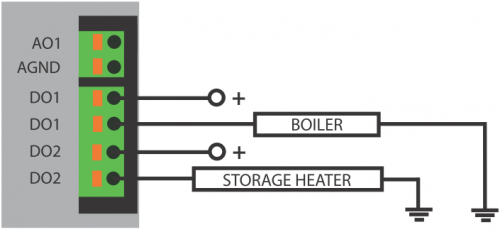
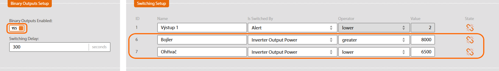
Digital (relay) outputs DO should be connected in the same way as SM2-MU. E.g. to boiler or storage heater as shown in the following picture.
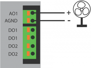
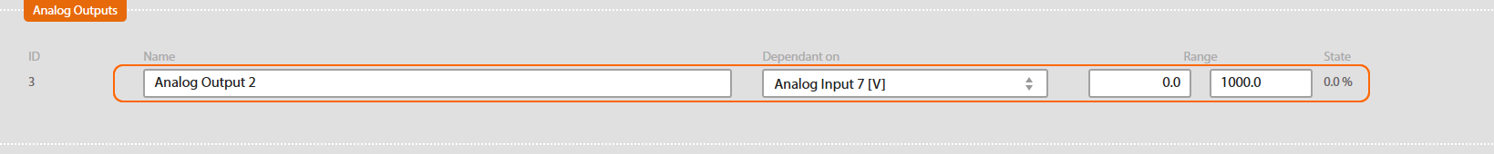
Analog output A0 should be connected in the same way. Voltage 0-10V at output terminals depends on current PV plant production or temperature. It could be used for smooth regulation of devices (e.g. ventilator).
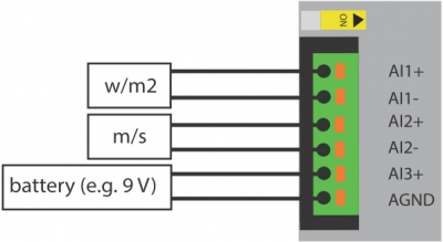
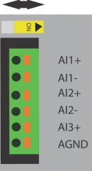
With each analog input AI1, AI2 and AI3 you can use following ranges: 0 - 20 mA, 0 - 10 V, 0 - 20mV, 0 - 100 mV to measure voltage or current. Measuring range is set up before modules are delivered! Be careful to choose the right range when ordering SM2-AD module. A pyranometer (measures exact irradiation values), an anemometer (measures wind velocity) or battery (to get info of its state) can be connected to the outputs.
Multiple connection of SM2-AD modules
It is possible to connect up to 8 SM2-AD devices to the SM2-MU. In case there are two SM2-AD modules connected to one Solar Monitor unit, they need two separate addresses in order to communicate with SM2-MU. Use the yellow sliding switch to do that. In case there are more than two SM2-AD modules connected to the SM2-MU, you have to specify this fact when ordering the modules (sliding switch works with addresses 2-3, 4-5, 6-7, 8-9).
Start and configuration
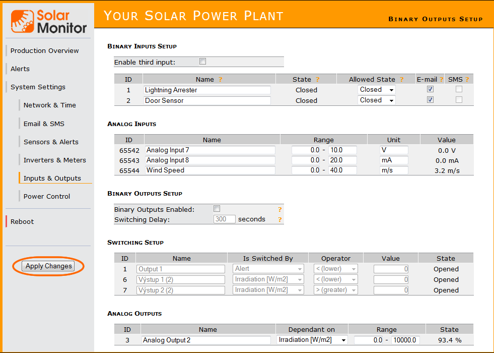
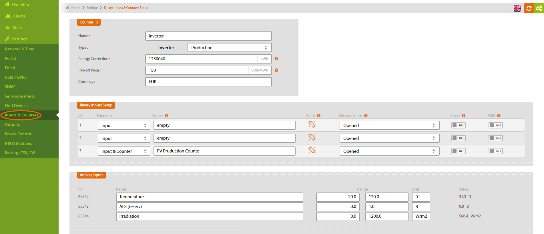
When you have connected the modules and Solar Monitor unit has been connected to the power supply, green LED diode indicating status should glow. If it doesn't glow, check the wiring of SM2-MU and the module. Open menu “System set up/ Inputs and Outputs” in your browser.
Digital output set up is the same as with DO1 output in SM2-MU. You have to allow the outputs and select starting condition (e.g. certain level of power production).
Setting up analog output is similar to digital. Select the key factor for setting up the output (e.g. temperature of the room where inverters are located). Then set up the temperature range for output value 0 - 10 V, that will control the ventilation.
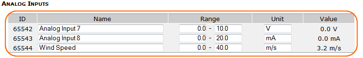
You need configuration document in order to set up analog inputs. In the document you find out the measuring range of each input (e.g. 0 - 20 mV). This range can be easily converted to e.g. measuring wind velocity. Suppose that 0 m/s = 0 mV and 30 m/s = 15 mV, we can convert these values into the measuring range:
“measuring range maximum”
———————————- * “value that measuring range maximum represents”
“measured range maximum”
In our example:
20
— * 30 = 40
15
We enter this figure as maximum of the range and enter the required units of measurement. Measured values are shown among other sensor values.
When you have entered the changes, click the button Save.