Solar Monitor User Guide
- Quick Setup
-
- Overview
- How to Install?
- Quick Start
- Factory Reset
- Web
-
- Extension Modules
![]()
SM2-MU unit has been designed for indoor usage. When used outdoor, it requires sufficient protection from external impacts and the range of operational temperatures must be respected. The values concerned to be found in chapter Module parameters.
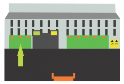
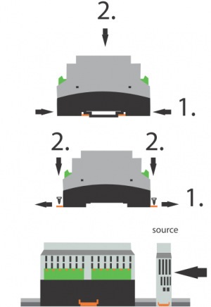
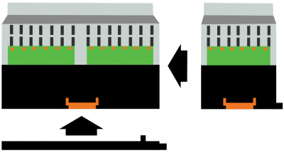
Click shut the module onto the DIN rail using orange hitches.
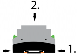
Click shut the power supply to the DIN rail in the same way.
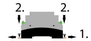
Use holes in the orange hitches to install the module on the wall. The hitches must be “opened”. To open the hitches press the safety catch with a pointed object (e.g. pen) first and then open the hitch. The same for the second hitch. Insert the screw into the holes and fasten the unit on the wall.
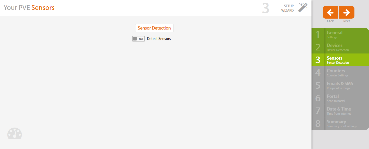
If there are no sensors connected to your SM2-MU device, go to Next >>
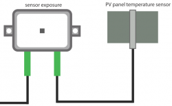
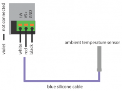
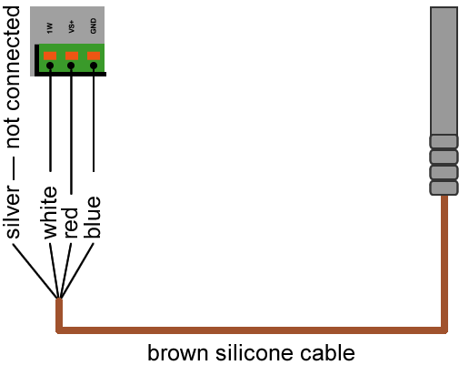
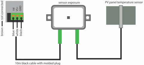
Connect the sensors to the SM2-MU according to the following pictures:
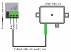
In this picture you see to which terminal on the SM2-MU connects each pin of the irradiance sensor.

To be connected with 10 meters cable with pressed-in connector. Connect the cable to SM2-MU terminals and the pressed-in connector to the irradiation sensor.
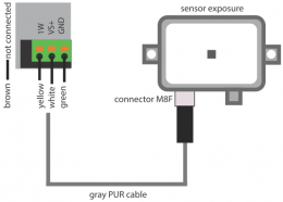
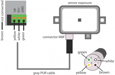
In case you use grey PUR cable with M8F connector, follow these instructions:
1. First connect separate lines of PUR cable to the pins of M8F connector.
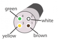
2. Connect the PUR cable to SM2-MU terminals and the M8F connector to the irradiation sensor.
Connect the pressed-in connector of PV panel sensor cable to the irradiation sensor.
Connect blue or brown silicone cable to the SM2-MU terminals.
Solar Monitor can operate up to 10 sensors. The total length of cabling must not exceed 100 meters. In case of multiple sensors connect each cable parallelly into the same terminals.
You can find several connection schemes of sensors here.
If there is no electro meter connected to your SM2-MU , go to Next >>
Solar Monitor is connected to the electro meter with its S0 (puls) output as shown in the following picture:

You can use any of 3 digital DI inputs to count energy from the meter.
Connecting in case both SM2-MU and electro meter each has its power supply:

If you don't intend to connect any inputs to your Solar Monitor, go to Next >>
Solar Monitor has 3 digital inputs DI available.
If DI input doesn't read the energy from the electro meter, it can be used as a standard digital input.
Connect DC- supply signal to DCOM terminal. In order to switch the input on, voltage between terminals DCOM and DI (DI1-DI3) must be higher than 8V.
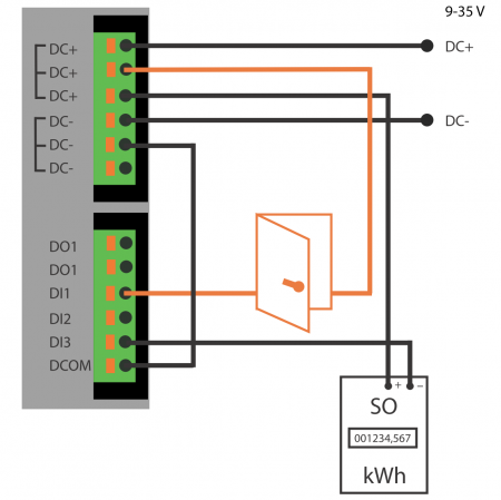
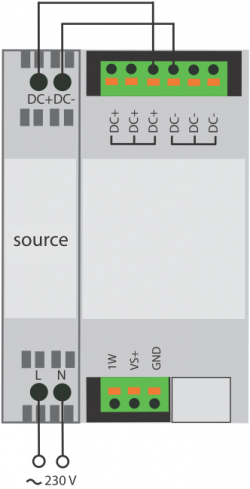
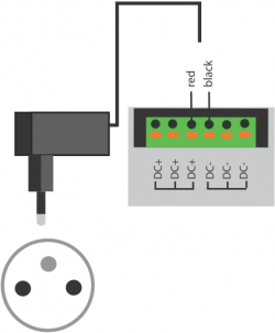
Connect the power supply (9-35V) to SM2-MU unit as shown in the following pictures.
SM2-MU unit allows DHCP client regime in the default setting. The IP address is allocated automatically by the DHCP server in local net (if available).
In case you don't have DHCP server in your net, for firmware version 2.2.0 Build 51 or higher follow these steps:
1. In Solar Monitor press button Setup and keep holding.
2. Connect the power supply.
3. When power supply has been connected, wait until Status diode starts flashing green light (takes about 5 sec), let go off Setup button and then press it 3 times.
4. Within 10 seconds you will be able to connect at the permanent IP address 192.168.1.99.
In case your Solar Monitor has firmware version older than 2.2.0 Build 5up button1, follow these steps:
Connect the unit to the power supply and when green LED diode Status starts glowing, press Setup button 3 times.
Within a few seconds you will be able to connect at the permanent IP addres s 192.168.1.99.
When you enter this IP address into your browser, you will find unit's web interface.
Application ETool makes finding SM2-MU on the net easier.
This application enables finding your unit with any IP address setting. Application to be downloaded here and then you can install it in your PC.

Button  next to “IP address“ opens website of chosen unit. See chapter Web interface.
Unit's website can also be opened with a click on Device Image.
If there is no counter connected to your Solar Monitor (electrometer, gas meter, inverter, tracker, batery or another meter), go to Next >>

First you need to allow the chosen input, then you will be able to set it up.

Select particular counter.

For details about this settings see chapter Inputs & Counters.
Click on Next on the right to get to the next step.
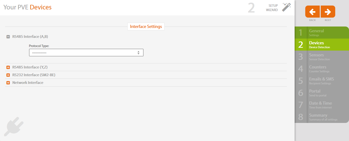
Select interface for communication with the inverter and then protocole type and transmission speed.
After that click on Next button on the right to get to the next step.
For more detailed info on setting go to chapter Find Devices.
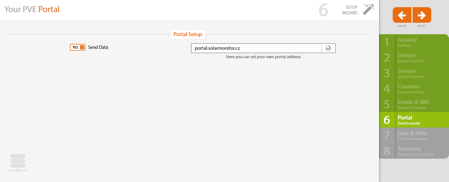
When you enable sending data from devices connected to SM2-MU, data will be saved at the Portal.
Portal Solar Monitor gives you possibility of detailed analysis and reporting to ![]() .
.
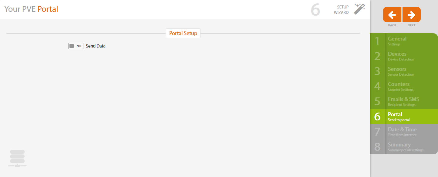
In case you want to send data to the Portal, tick YES and enter the Portal's address (e.g. portal.solarmonitor.cz)
Click on Next on the right to get to the next step.

The Solar Monitor system is made by Czech company Solar Monitor ltd. All information and contacts to be found on www.solarmonitor.cz. Our product was developed to offer maximum convenience for controlling, continuous monitoring, invoicing and reporting of a PV plant in the Czech Republic.
Simple installation of the base module and expansion modules on the wall or DIN rail
Czech user interface
Easy to use
Maximum functionality
High reliability
Low power consumption
Easy configuration via web interface
Usage doesn't require installation of additional software on the PC
Weather conditions monitoring (air temperature, PV panel temperature, exposure, wind velocity and direction, and additional sensors can be implemented)
Monitoring the inverter status, error reading, operational data retrieving
Connection for up to 100 inverters (depends on type)
Electrometer shows the values of energy produced
Monitoring two contact inputs (e.g. theft, movement, optical barrier…)
Automatic alarm for sending e-mail or text message to the user for defined status (texting requires GSM modem)
In-built invoicing and reporting required by the Czech legislation
Optional connection to the portal offers the option of large-scale analysis
Connection of expansion modules (GSM module, Power control module, Analog Digital inputs and outputs module) available
Shows history of measured values for easy detection of a problem e.g. in network
Replaces data logger supplied by inverter manufacturer
| Max. number of devices1 | |
|---|---|
| SM2-MU Basic and SM2-MU Start | 1 device1 |
| SM2-MU 60 | 6 devices1 |
| SM2-MU 300 | 30 devices1 |
| SM2-MU 1000 | 100 devices1 |
| Supported devices1 | Ethernet or serial bus connected |
| Communication | Ethernet (TCP), up to 3 serial ports |
| Inverter protocols | AEG, Carlo Gavazzi, Danfoss, Delta, Diehl, Fronius, IBC Solar, Kaco, Kostal, Mastervolt, Morningstar, Omron, Pairan, Power‑One, Refusol, Riello UPS, Santerno, Satcon, Schneider‑Electric, Siemens, Siliken, SMA, Solarmax, Solutronic, Studer, Sungrow, Sunville, Sunways, Vacon, Xantrex |
| Meter protocols | ABB (REX521), Carlo Gavazzi (VMU-E/X), Fronius (Smart Meter), KMB (SMC-144, PA-144), Phoenix Contact (MA200/250), Schneider‑Electric (SEPAM, PM9), Yorix (GreenBonO), ZPA (IEC 62056-21) |
| Sensors | Dallas 1-wire bus |
| Interface | Screw terminals for 05 mm² - 15 mm² cores |
| Max. count | 10 sensors |
| Max. distance | 100 m, recommended max. cable length for daisy‑chained sensors with minimal trunk segments |
| Ethernet interface (LAN) | |
| Interface | RJ45 (100BASE-T) -100Mbit/s, compatible with networks 10/100/1000 Mbit/s, auto MDIX |
| Protocols | HTTP, SOAP, DNS, UDP Setup, Telnet, ARP, ICMP, SMTP, SNMP, Modbus |
| RS485 / RS422 / RS232 | |
| Interfaces | 2x RS485 or 1x RS4222 |
| piggy-back hardware options 3 | |
| 2x RS485 or 1x RS422 opto-isolated2 | |
| 1x RS485 + 1x RS232 | |
| 1x RS485 + 1x RS232 opto-isolated | |
| SM2-BE extension module | |
| 1x RS232 + 1x RS485 surge protected4 | |
| Speed | 300 .. 115.200 bps (software configurable)2, 5 |
| Termination | Yes, both for half and full duplex, configurable with jumpers |
| Inputs | opto-electronically isolated |
| 3x digital inputs (DI) | software configurable between dry contact or S0 pulse meter inputs (e.g. from electrometer) |
| Max. distance | 30 m (depends on cable) |
| Outputs | |
| 1x relay | 32 V, 3 A, protected with power fuse |
| Electrical parameters | |
| Power supply | 9-35 V DC, typ. 1.2 W @ 12V |
| DI1, DI2, DI3 | 8-80 V |
| 1 Wire | Interface provides 5 V power supply, max. 350 mA, protected with 500 mA power fuse. |
| RS485 | Protected against transient voltages above 6.8V and against high currents with 10Ω resistors. Additional surge protection can be achieved with SM2-BE (bus extension) module with gas discharge tubes: |
| Minimum DC Sparkover (100 V/s) 185 V | |
| Service life: | |
| 150 operations 8/20 μs 250 A, 1.2/50, 500 V (IEC61643-21) | |
| 20 operations 2/10 μs, 5 kV, 500 A | |
| 2 operations 8/20 μs, 1 kA | |
| Mechanical parameters | |
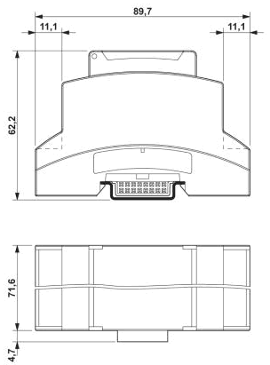
| Dimensions | 71.6 x 89.7 x 62.2 mm |
| Mounting | DIN rail |
| Screw terminals | 05 mm² - 15 mm² cable cores |
| Degree of protection | IP20 |
| Operating temperature | 0 .. +70 °C |
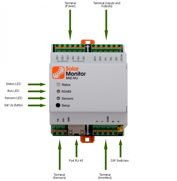
| LED diodes | Status, RS485, Sensors |
| Extension options | |
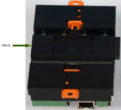
| Interface | HBUS (DIN rail, bottom pluggable, no external wires needed) |
| Extension modules | SM2-PC, SM2-AD, SM2-DI, SM2-GSM, SM2-BE |
1 … A device represents an inverter, stringbox, MPP tracker, battery monitor, meter or any other device which can be detected on any serial bus or via ethernet communication.
2 … Can be configured by software (web UI, XML).
3 … Piggy-back functionality replaces the “2x RS485 or 1x RS422” interface.
4 … SM2-BE is mutually exclusive to the SM2-GSM usage. 2x SM2-BE modules can be also used to extend the HBUS connection between SM2 modules.
5 … Communication speeds are available according to selected device communication protocols.
 Before you start using our device, please read safety warning and operating instructions included in this manual. Device works in accordance with Czech regulations. It has been tested and is delivered in serviceable conditions. To maintain these conditions you should follow bellow mentioned safety and maintenance requirements.
Do not use the device if:
Manufacturer accepts responsibility for the device only if it uses power supply provided or approved by manufacturer.
The connection of signal lines to the inverter must comply with the requirements of ČSN EN 61643-21 + A1, A2 and ČSN EN 62305-1 ed.2. Otherwise, the manufacturer will not be liable for damage to the equipment.
Notice:
To install Solar Monitor system special tools are necessary e.g. crimping pliers for installing RJ45 connector.
Solar Monitor unit is designed for indoor installation. When placed outdoor it needs sufficient protection from external influences and respecting operational temperature range is essential. You will find the data in the chapter Parameters of basic module.
Solar Monitor unit plus expansion modules can be fastened on the wall or DIN rail as shown in the pictures bellow.
Solar Monitor unit can connect up to 10 sensors. Maximum length of cables must not exceed 100 meters. Following sensors with cables can be connected. In case of multiple sensors use parallel connection into the same terminal.

To connect SM2-MU and irradiation sensor in distances longer than 10 m, grey PUR cable with M8F terminal must be used.
Terminals SM2-MU: A, B, SGND, Z, Y, or DC+ a DC - are used according to the inverter manufacturer.
If there is SM at the beginning of H-bus, sliding switches must be in ON position.
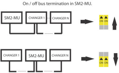
The same for the inverter - if it supports bus termination, the last one should be switched on according to the manufacturer's instructions. Description of inverter connection to the Solar Monitor unit and whether it supports the bus is to be found in the following table.
If there is manual address scheme in your inverters, you need to set up addresses, ideally beginning with address 1. E.g. 21: 1, 2, 3, …, 31. Procedure is described in inverter's manual. Usually set up with DIP switches or in LCD inverter menu.
| SM2-MU | Z | Y | SGND | B | A | DC+ | DC- | Bus termination | Hand addressing | Transmission speed |
|---|---|---|---|---|---|---|---|---|---|---|
| AEG | 4(Rx-) | 3(Rx+) | 1(GND) | 5(Tx-) | 6(Tx+) | - | - | ✔ | - | 9600 |
| Power - One (Aurora) | - | - | RTN | -T/R | +T/R | - | - | ✔ | ✔ | optional |
| Carlo Gavazzi | - | - | 5(GND) | 8(RXB) | 7(TXA) | - | - | ✔ | - | optional |
| Danfoss | - | - | 1 | 3 | 6 | - | - | ✔ | - | 19200 |
| Delta | - | - | GND | 6 | 7 | - | - | ✔ | ✔ | optional |
| Diehl | - | - | shield | B | A | - | - | ✔ | - | 19200 |
| Fronius IN OUT | 5 6 | 4 3 | 2 2 | 6 5 | 3 4 | - - | - - | ✔ ✔ | ✔ ✔ | optional optional |
| GreenBonO | - | - | - | B(-) | A(+) | - | - | - | - | 9600 |
| Kaco | - | - | - | A | B | - | - | ✔ | ✔ | 9600 |
| KOSTAL | - | - | 3 | 2 | 1 | - | - | ✔ | ✔ | 19200 |
| Mastervolt | - | - | - | 3 | 4 | - | - | ✔ | - | 9600 |
| Omnik | 5(Rx-) | 4(Rx+) | 7(GND) | 6(Tx-) | 3(Tx+) | - | - | ✔ | - | 9600 |
| Omron | - | - | 6: GO | 8: A- | 7: B+ | - | - | ✔ | ✔ | optional |
| Refusol | - | - | - | 3 | 2 | - | - | ✔ | ✔ | 57600 |
| Santerno | - | - | - | S- | S+ | - | - | ✔ | - | optional |
| Schneider (SunEzy) | 4(Rx-) | 3(Rx+) | 1(GND) | 5(Tx-) | 6(Tx+) | - | - | ✔ | - | 9600 |
| Siemens | - | - | - | B | A | - | - | ✔ | ✔ | optional |
| Siliken | - | - | 5(GND) | 8(RXB) | 7(TXA) | - | - | ✔ | - | optional |
| SMA | - | - | 5 | 7 | 2 | - | - | ✔ | - | 1200 |
| Solar Max | - | - | 8 | 7 | 2(15V) | 3 | - | ✔ | ✔ | 19200 |
| Steca | - | - | 8 | 2 | 1 | 4 | 7 | ✔ | ✔ | 38400 |
| Studer | 2 | 3 | 5 | - | - | - | - | ✔ | - | 115200 |
| Sungrow | - | - | 3 | 6 | - | - | ✔ | ✔ | optional | |
| Sunville | 4(Rx-) | 3(Rx+) | 1(GND) | 5(Tx-) | 6(Tx+) | - | - | ✔ | - | 9600 |
| Vacon | - | - | 5 | 3 | 4 | - | - | ✔ | ✔ | optional |
| Xantrex (GT100-630E) | - | - | GND | RxTx- | RxTx+ | - | - | ✘ | optional | optional |
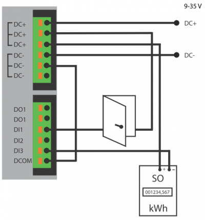
Solar Monitor can be connected to Green Bonus electro meter via any of three binary inputs DI. It reads the energy output of your PV plant.
The following picture shows how to connect to the electro meter with S0 (puls) output:
In order to get the right data, the right number of pulses per 1 kWh must be set up in the unit.
Default setting is 1000 pulses per 1 kWh. If your electro meter has different number of pulses, change the default setting value.
In the electro meter's label or documentation find out how many pulses per 1 kWh your electro meter generates at the SO output. Fill in this value into relevant box in SM2-MU menu Inputs & Counters.
In the electro meter's label or documentation find out how many pulses per 1 kWh your electro meter generates at the SO output. Use this number in calculation, see example bellow.
Example: Electro meter's label states 10 000 impulses per 1 kWh.
Look at the indirect power measuring transformer (1 transformer connected to each phase) and find a ratio (e.g. 150A/5A). Use the result of this ratio (30 in this example) in the formula (10 000/30). Fill in the result into relevant box in SM2-MU menu Inputs & Counters.
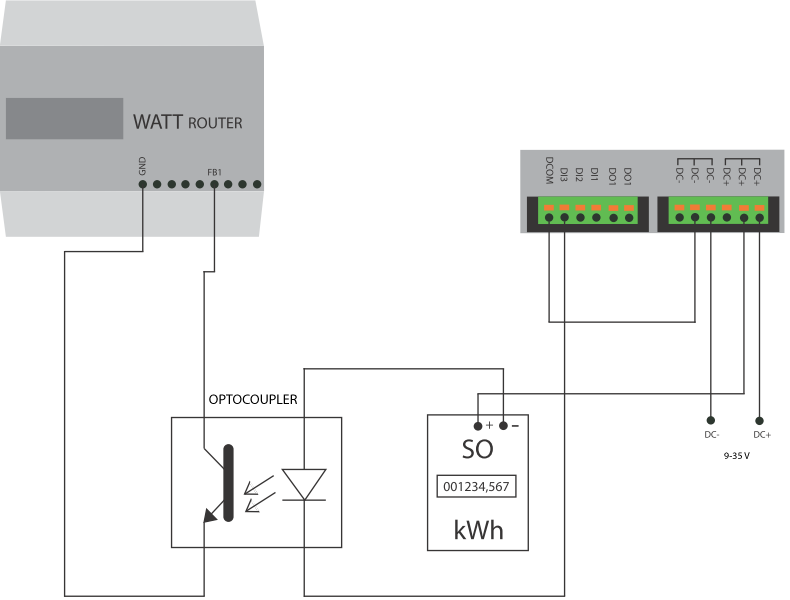
In case you want the electro meter connected to the Solar Monitor and use pulse output for another device (e.g. Wattrouter) at the same time, follow instruction in the next picture:
In order to communicate with the user, Solar Monitor must be connected to ethernet (LAN). There is one port RJ-45 available, the same as in PC's. The unit is connected to the net in the same way as PC.
Connect the unit into LAN (to the switch or PC) with a straight or crossover UTP cable. UTP cables for connecting to LAN are available in PC shops.
Straight UTP cable = both ends are the same (T568A)
Crossover UTP cable = T568A + T568B
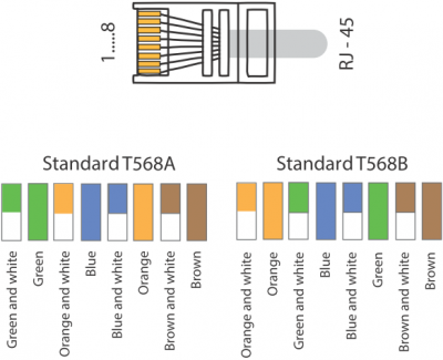
The device is connected to the net if a green LED light “LINK”at RJ45 terminal of SM2-RM switches on.

Solar Monitor has 3 digital inputs DI. It is easy to connect movement sensor, surge, optical barrier, door sensor and various other devices that use contact inputs to indicate its status. Any of the inputs DI1, DI2, DI3 can be used for measuring energy at the electrometer on condition that it has pulse output SO.
Pulse output S0 is a special measuring output where there the electrometer generates pulses by switching. Solar Monitor unit counts the pulses and converts the pulses to kWh in selected conversion coefficient.
Conversion coefficient differs according to the electrometer's type and in most cases it doesn't correspond with the number of LED diode pulses. It is very important to select the right coefficient for SO output. Most electrometers have 250/kwh number of pulses at the LED diode and 1000/kwh at the output SO. You will find out how to enter the right coefficient into Solar Monitor unit in chapter Inputs & Counters.
In order to use inputs you have to bring power signal DC- to the terminal DCOM . In order to switch on the input you have to bring power signal DC+ to appropriate terminal DI.
It is possible to connect more devices to a single contact loop and monitor the entire circuit as one name. But if one device changes contact status, you won't be able to identify which device has caused the alarm.
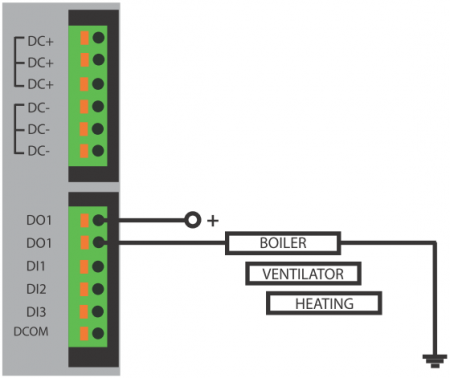
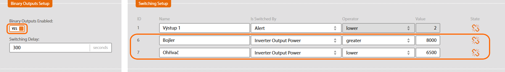
You can choose one relay which is in SM2-MU. The relay can switch on the ventilation according to current ambiente temperature or it can control the boiler (must be connected via contactor) according to the current energy production etc.

Po zapnutí napájení se rozsvítí zelená led dioda Status. Zároveň se rozsvítí zelená dioda u síťového konektoru a začne současně problikávat oranžová.
V továrním nastavení má jednotka povolen režim DHCP klient, kdy získá IP adresu automaticky od DHCP serveru v místní síti (pokud je dostupný).
V případě, že nemáte DHCP server ve Vaší síti, postupujte pro verzi firmware verze 2.2.0 Build 51 nebo vyšší takto:
1. Stiskněte na Solar Monitoru tlačítko Setup a držte ho.
2. Připojte napájení.
3. Po připojení napájení vyčkejte cca 5 sekund až začne dioda Status zeleně blikat, pusťte tlačítko Setup a poté ho 3x stiskněte.
4. Do 10 sekund je možno se připojit na pevné IP adrese 192.168.1.99.
V případě, že má Solar Monitor starší verzi firmware než 2.2.0 Build 51, postupujte takto:
Připojte jednotku k napájení a jakmile se rozsvítí zelená LED dioda Status, stiskněte 3x tlačítko Setup.
Po několika vteřinách je možno se připojit na pevné IP adrese 192.168.1.99.
Pro usnadnění vyhledávání SM2-MU na síti slouží aplikace ETool.
Tato aplikace nalezne Vaši jednotku nezávisle na nastavení IP adres. Aplikaci si můžete stáhnout zde a poté nainstalovat do Vašeho PC.
ETool
Program s názvem ETool umožňuje nalézt zařízení na síti, zařízení nakonfigurovat,
nastavit defaultní hodnoty celého zařízení a restart zařízení.
Tato utilita se instaluje na PC s operačním systémem Windows. Pro její funkčnost je nutné
povolit odesílání broadcast paketů přes Windows firewall.
V seznamu se objeví všechna zařízení od společnosti Solar Monitor s. r. o. připojená k místní síti. Nově nalezená zařízení jsou v seznamu zvýrazněna modrou barvou.
Výběrem příslušného zařízení v seznamu je možno upravovat jeho nastavení, včetně resetování do továrního nastavení.
Tlačítko vedle pole “IP adresa“ otevře stránky vybrané jednotky. Viz kapitola Webové rozhraní.
Stránky jednotky lze taktéž otevřít vlevo dole proklikem přes Obrázek zařízení.
At this point, you have set up the IP address and network mask in the Solar Monitor unit. If not, please return to chapter Unit discovery in a LAN. This chapter focuses on opening unit's web interface on the internet browser.
In order to connect to the unit use the internet browser and set the address http://192.168.1.99 or IP address automatically stipulated by DHCP server.
“Address” box in the internet browser is situated at the top of the browser, where you enter e.g. www.seznam.cz.
After you have connected to the unit you need to set everything to suit your requirements. Menu ” System setup” and submenu will help you.
MAC Address
MAC address identifies each network device. It is not possible to change it. All units SM2-MU begin with 70:B5:99.
System Version
There is the type of the unit (Solar Monitor Basic / Start / 60 / 300 / 1000/ RM/ RM-GSM).
Firmware Version
There is current version of the unit software.
Web Version
There is current version of unit web interface.
Runtime
It shows the period since the unit was switched on for the last time.
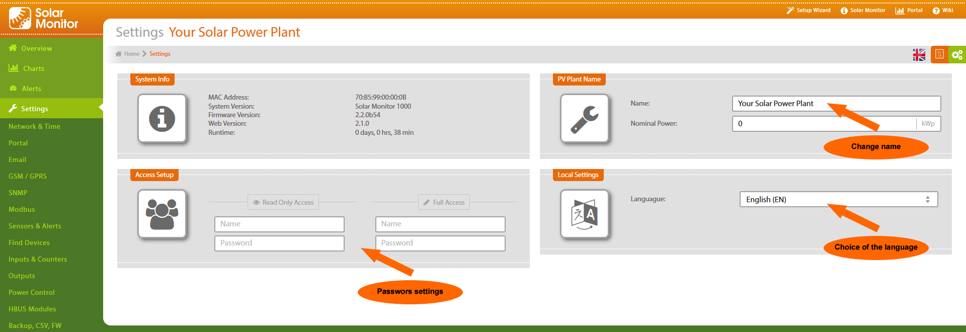
Name
Enter the name of your PV plant - visible in the web header, e-mails and text messages. (Note: text messages SMS do not have diacritics!)
Read Only Access
Set the user name and password for reading access. Users who don't know the password cannot access Solar Monitor unit websites. A logged in user with ” reading only access” is not allowed to change the setting, but he can see all information sites.
Full Access
Set user name and password for full access. User with full access may use all function of the Solar Monitor unit.
This submenu enables setting the network and time.
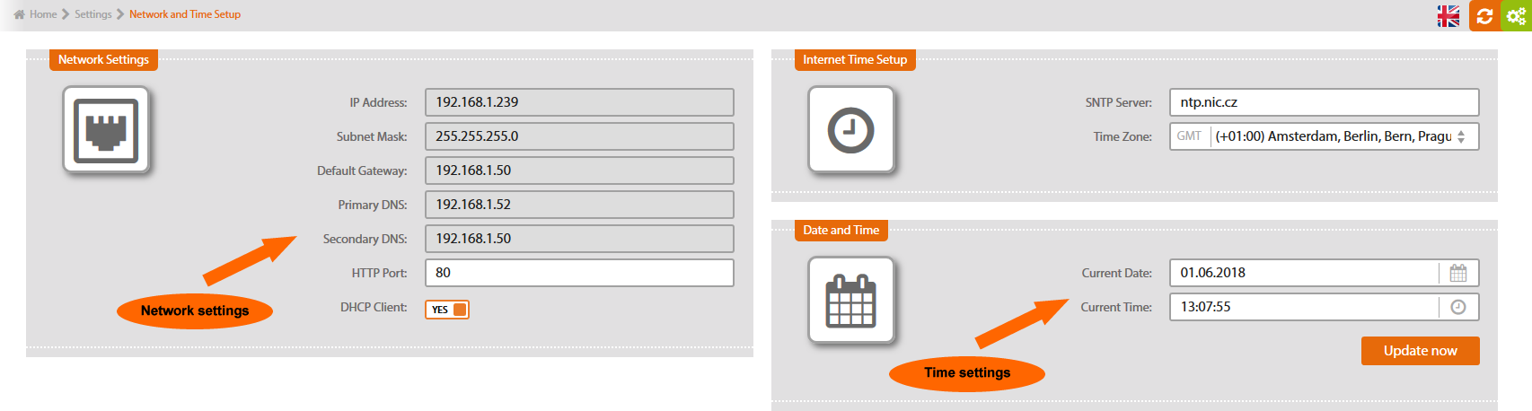
IP Address
Enter the IP address out of the range of network that Solar Monitor uses.
Network Mask
Enter the network mask corresponding to the Solar Monitor's network.
Default Gateway
Enter the local net address of a device that serves as default gateway to other nets. In local nets it is mostly ADSL modem or some kind of a router (e.g. WiFi router). Without the default gateway the unit won't have the internet access (functions Internet Time and Sending to the Portal won't work).
Primary DNS, Secondary DNS
These are servers responsible for translating domain names to IP addresses. Without them the unit isn't likely to have the access to the internet. Your network administrator or provider should inform you about the correct setting.
HTTP Port
Default setting: 80. You can change the port where the Solar Monitor unit accepts web interface clients. If you set up another port, you have to enter it in the Address box in your browser (e.g. 192.168.1.99:81).
DHCP Client
DHCP client regime enables the unit to get an entire IP configuration (i.e. IP address, network mask, default gateway, primary DNS, secondary DNS) from a DHCP server of the particular network, in case you have got that server, of course. DHCP server function is integrated in most current ADSL modems and WiFi routers, and local networks can usually use that function.
If your unit “disappears” in the network after you have switched on DHCP client, you can find it with ETool utility, which can be downloaded here.
SNTP Server
Enter time server address on the internet. Default: time.nist.gov.
Time Zone
Select your time zone.
Current Date
Set/check the right date. This item is updated automatically from the SNTP server on the internet.
Current Time
Set/check the right time. This item is updated automatically from the SNTP server on the internet. Button “Update now” synchronizes the time with the server.
You can set up email in this submenu.
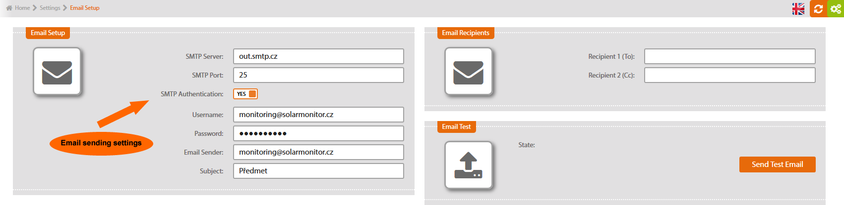
SMTP Server
Enter the server for outgoing mail. If you have an email account at a free-mail server (e.g. seznam.cz), you can use that account. Your internet provide or network administrator will inform you.
SMTP Port
Enter the port for outgoing mail. Default setting “25” is usually OK. For further info contact your SMTP server operator.
SMTP Authentication
SMTP servers usually require name and password authentication. To permit this authentication tick the box.
Username, Password
Enter log in for the SMTP server
Email Sender
Enter sender's email address (Solar Monitor unit). Recipient will see this as sender's address.
Subject
Enter the text into the subject box.
Recipient 1(To), Recipient 2(Cc)
Enter recipients' addresses. You can check if it works with the button. If no e-mail has come, check SMTP set up (section “Email set up”).
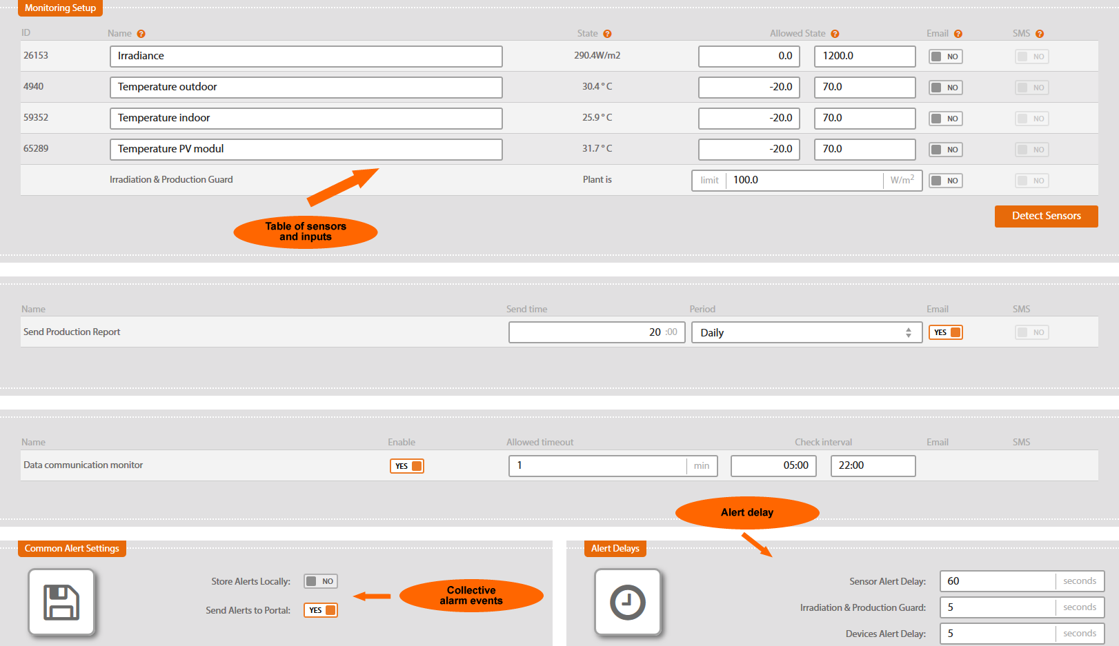
There are all sensors, inputs and electrometer in the table. To connect the sensors to the unit, run auto-detection - button ” Search sensors”.

Once found, all sensors and the values are displayed. This table enables changing their names, limits and way of informing about exceeding the limits.
Send Production Report
A message about monthly or daily generated energy is sent in selected hour.
Connection Failure
In case that Solar Monitor stops receiving impulses from the electrometer in preset interval, this function notifies the user. You can set the delay since the last impulse received.
Data communication monitor
In case of detected device (e.g. inverter, tracker) connection failure it sends alarm to the portal.

Store Alerts Locally
Every alarm is recorded in to history if you choose this option (menu Alerts \ System Log). With this option on, every record in history reduces total capacity of measured values in the unit.
Send Alerts to Portal
If sending is permitted, with each alarm there will be a special packet sent to the portal. The packet contains info about the alarm and current values.
This is possible if you have set up the portal (see chapter 4.1.1 Submenu Network and Time).
Sensor Alert Delay
You set up the delay between the time when alarm appeared and the time when it is reported. This delay prevents sending many alarm reports with sensor values just about the set values.
Irradiation & Production Guard
You set up the delay between the time when alarm appeared and the time when it is reported. This delay prevents sending many alarm reports with irradiation values just about the values preset in monitoring. (earlier on this page).
Devices Alert Delay (e.g. from inverters)
You set up the delay between the time when alarm appeared and the time when it is reported. This delay prevents sending many alarm reports with inverter values just about the set values.
Submenu find devices enables setting up connected devices (inverters, MPPT trackers, meters) via RS485, RS232, ethernet interfaces.
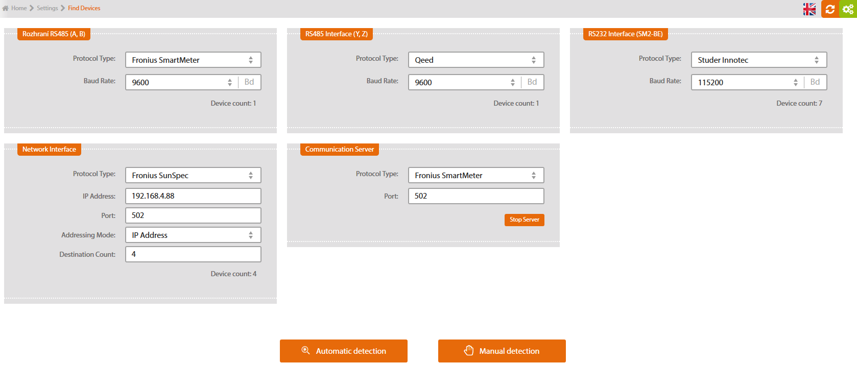
Select the type of communication. Relevant information is stated in documentation for the device.
RS 485
RS 232
Net interface (Ethernet)
To be set up in the submenu Find Devices

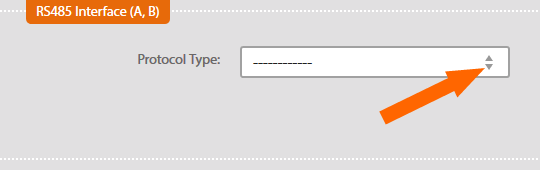
Type of Protocol
Select manufacturer of your device.
For inverter with full duplex connection only parameters for A and B must be set up.
For inverter with half duplex connection you can choose terminals A,B or Y,Z. Another option is connecting multiple inverters in two branches. One branch is to be connected to A,B terminals, second one to Y,Z terminals. More info on how to connect inverters here.
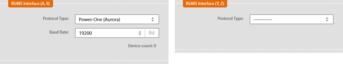
Bit Rate
Select bit rate. All inverters and Solar Monitor unit must have the same value. Info on bit rate (its value or changing the value) to be found in inverter's documentation or in communication card's documentation.

Read Connected Inverters
Press button  in order to detect inverters connected to SM2-MU.
Detection can take up to several minutes depending on the type of protocol.
Inverters must be on, i.e. they must have sufficient electrical current coming from PV panels.
When the detection is finished, the list of connected inverters is displayed.
Save the changes you have made  .
.
For detailed info on inverter's production click on a particular inverter in the menu Production Overview.
To be set up in the submenu Find Devices
Type of Protocol
Select manufacturer of your inverter.

Bit rate
Select bit rate. All inverters and Solar Monitor unit must have the same value. More info on bit rate (its value or how to change it) to be found in the inverter's documentation or in communication card's documentation.

Read Connected inverters
Press button in order to detect inverters connected to SM2-MU.
Detection can take up to several minutes depending on the type of protocol and number of inverters.
Inverters must be on, i.e. they must have sufficient electrical current coming from the PV panels.
When the detection is finished, the list of connected inverters is displayed.
Save the changes you have made.

For detailed info on inverter's production, click on a particular inverter in the menu Production Overview.
To be set up in the submenu Find Devices
Type of protocol
Select the manufacturer of your inverter.

Setting up network interface has two address modes:
1. IP Address - communication in local network
2. Port - remote communication via public IP address of router with translation of addresses (NAT)
Use this type of detection if inverters and Solar Monitor are in the same local network.
Address the inverters first. Assign consequent IP addresses to the inverters and the port number. The port number is the same for all inverters. Further info on how to address the inverters to be found in inverter's documentation.
IP Address
Enter inverter with the lowest IP address in the network. Detection starts with this address and searches for following higher IP addresses until the required number of destinations has been searched.
 Port
Port
Enter port's number.
Addressing Mode
Select addressing mode depending on the IP address.
The number of destinations
The number of IP addresses of all devices.
Detected devices
The number of devices assigned to each destination.
Read Connected Inverters
Click on button to detect inverters connected to SM2-MU
Detection can take up to several minutes depending on the type of protocol and the number of inverters.
To be detected, inverters must be on, i.e. they must have sufficient electric current coming from the PV panels.
When detection is finished, the list of connected inverters is displayed.
Save changes you have made.
For detailed info on inverter's production, click on a particular inverter in the menu Production Overview.
Select this method of detection if there is a router with network address translation (NAT) between the inverters and the Solar Monitor. The Solar Monitor will access to the inverters via one router´s address. Assign different, consecutive ports for the local IP addresses of the inverters in the router. If the router is connected to the Internet, router´s IP address must be public.
Address the inverters first. Assign different IP addresses to the inverters in your local network. In the router through which the Solar Monitor will access to the inverters, assign consecutive port numbers to the local IP addresses of the inverters. Further info on how to address the inverters to be found in inverter's documentation.
IP address
Enter the public IP address which you use for the access to the local network.
 Port
Port
Enter inverter with the lowest port number (destination) at a particular IP address. Detection starts with this port and searches for following higher port numbers until the required number of destinations has been searched.
Addressing mode
Select addressing mode according to the port.
The Number of Destinations
The number of ports where the devices have been addressed.
Detected devices
The number of devices assigned to each destination.
Read connected inverters
Click on buttonto detect inverters connected to SM2-MU.
Detection can take up to several minutes depending on the type of protocol and the number of inverters.
To be detected, inverters must be on, i.e. they must have sufficient electric current coming from the PV panels.
When detection is finished, the list of connected inverters is displayed.
Save the changes you have made .
For detailed info on inverter's production, click on a particular inverter in the menu Production Overview.
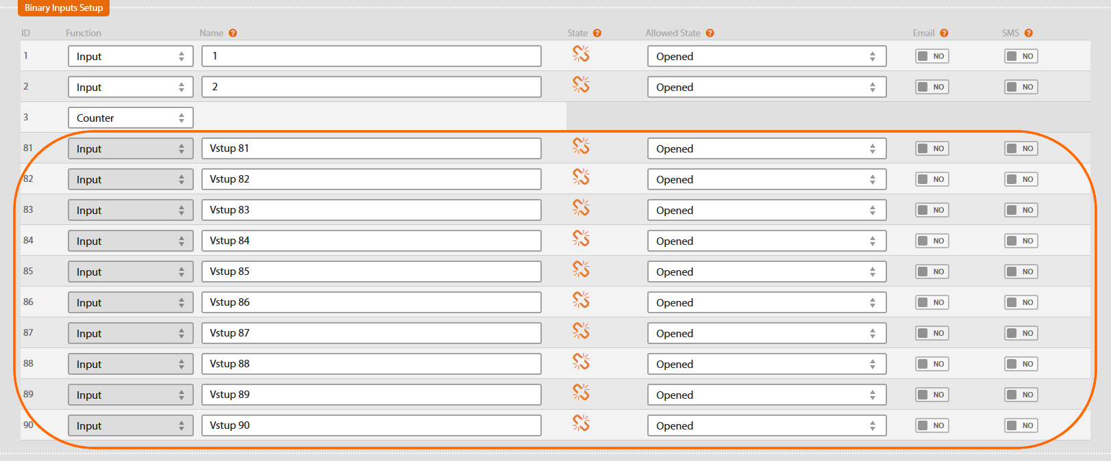
Submenu Inputs and Counters enables setting up inputs.
Default setting of the chart

Select input function
Solar Monitor has 3 inputs available. Each works as:
This chart presents current input status. Set up allowed value for them.

Choose if you want to receive report (by email or SMS) when input changes status (on/off).
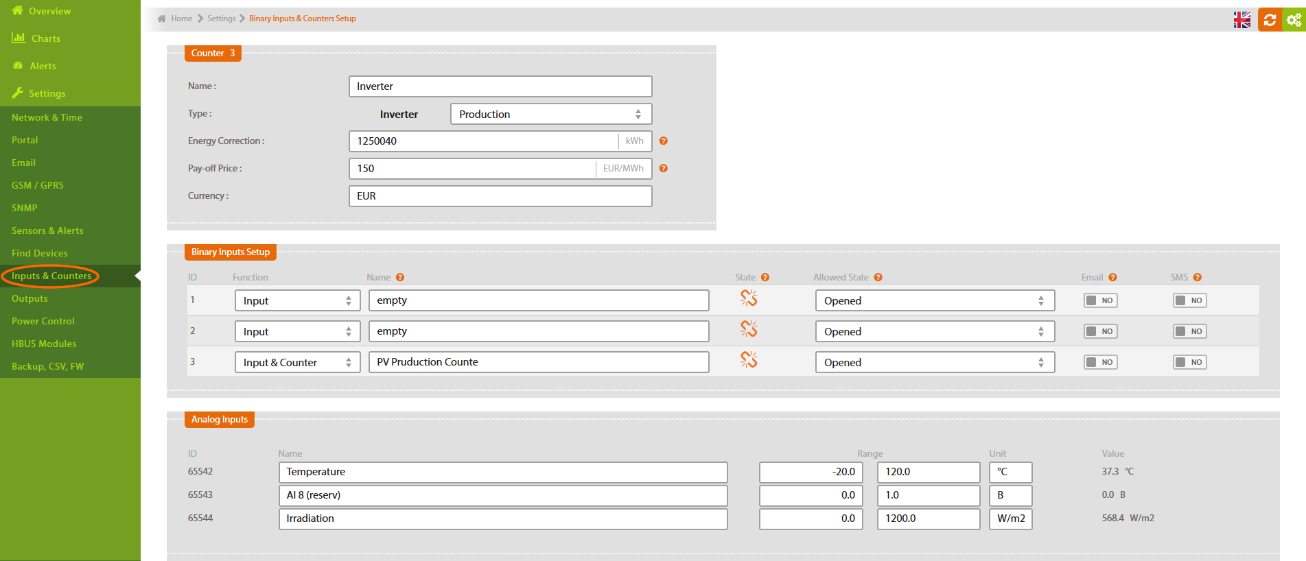
In the chart Inputs and Counters select function Counter for the particular input where meter is connected.
Meter can be connected to any of the 3 inputs. There can be up to 3 meters at each SM2-MU.

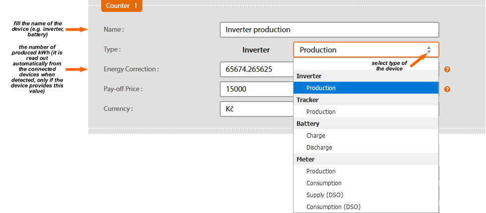
After you have chosen function Counter, its setup chart appears.

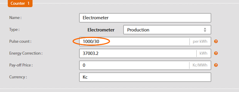
Enter its name (e.g. electrometer) and select its type.
Enter the correct number of pulses per 1 kWh (as specified in SO output at the counter).
In default setting there is 1000 pulses per 1 kWh. If your electrometer has a different number of pulses, you need to change this value in the chart.
Number of pulses per 1 kWh is normally between 250-1000 imp/1kWh. If your electrometer has two numbers of pulses, the right SO output number is usually the lower one.
Higher number says how many times light diode at the electrometer flashes.

Follow the instructions if you need to set up number of pulses other than 1000 per 1 kWh:
Find out how many pulses per kWh does your electrometer generate at SO output. This information is available at the label or in its documentation. Enter this number into the box Pulses Count in SM2-MU.
Find out how many pulses per kWh does your electrometer generate at SO output. This information is available at the label or in its documentation. Use this number for the following calculation .
Example: Electrometer specification says there is 10 000 pulses per 1 kWh.
Check transformer of indirect power measurement which is connected to electrometer (each phase one transformer). You should find a ratio (e.g. 150A/5A). Calculate the ratio (150:5=30 in this example). Use the result number (30 in this case) in this formula 10 000/30. Enter this number into the box Pulse Count.
If you enter incorrect number of pulses, Solar Monitor will be unable to present correct information about the power production. If the counter does't read the pulses, please check electrometer's cables and connection polarity.

After you have chosen function Input and Counter, a chart of Counter setup appears.
If there is e.g. inverter production selected, there will be total sum of all detected inverters in Production summary.
In case you use this input as binary, set up its allowed value.
After each change in settings, don't forget to press button .
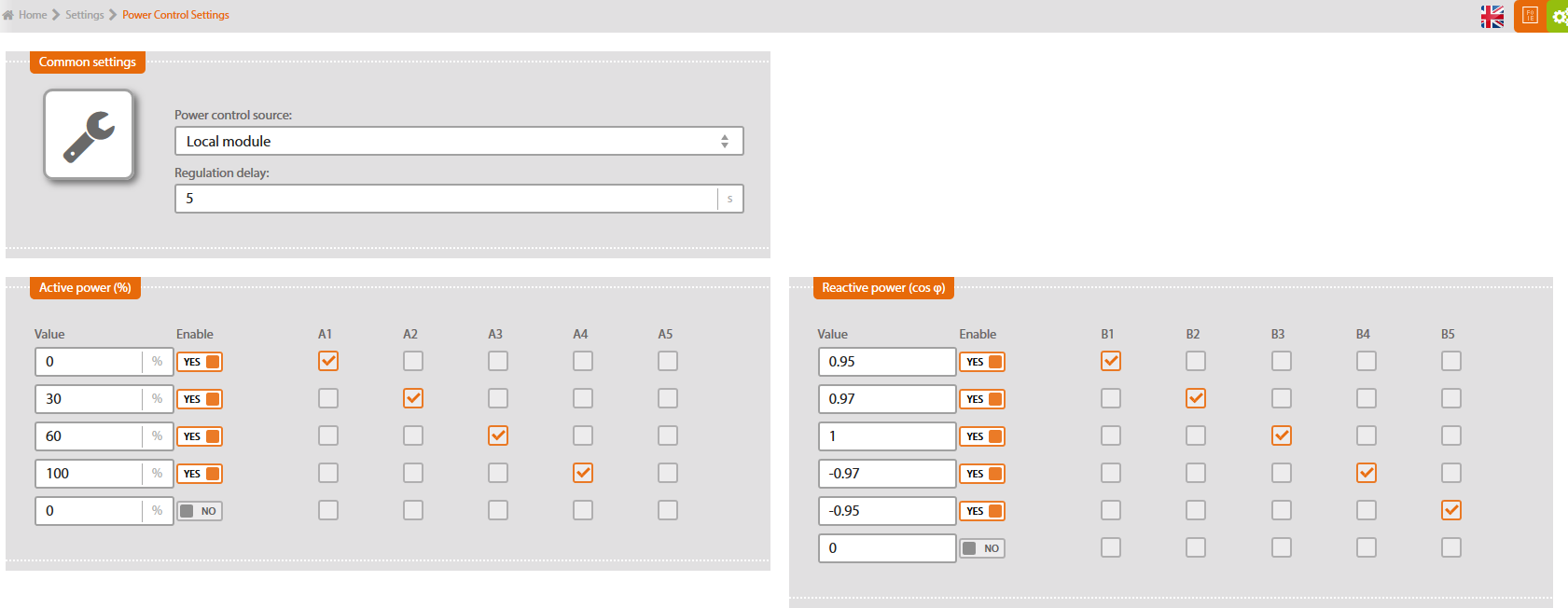
This submenu enables setting up power control module correctly.
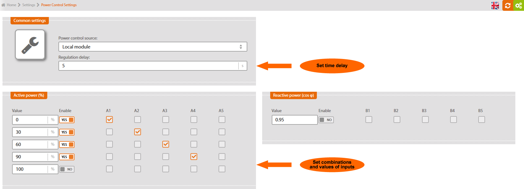
Power control source
Local module: Solar Monitor unit, with module SM2-PC directly connected.
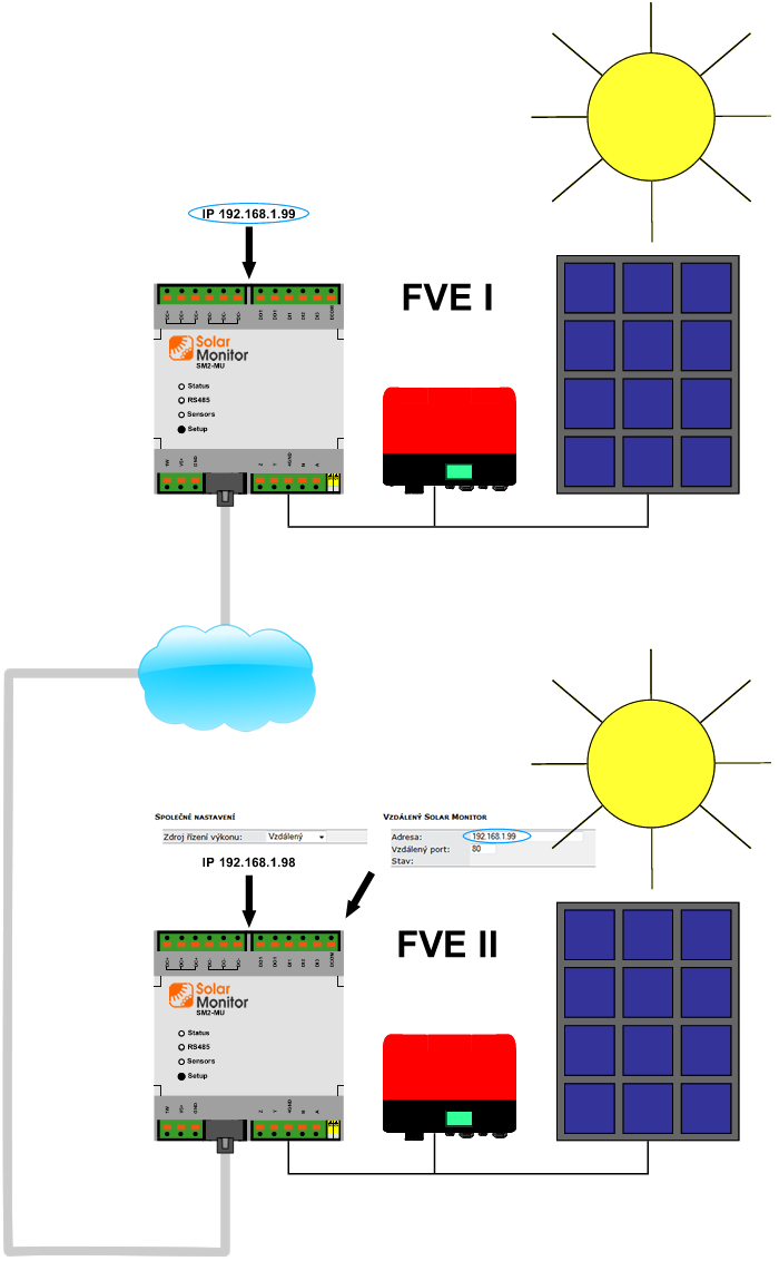
Remote: if you want to use power control module for other Solar Monitor units, which are in the same network as unit directly connected to SM2-PC, select option “Remote” for these units. These units don't need SM2-PC module then. Control options are configurated in local module.
Set up inputs combinations and corresponding values for power control (in %).
Set up inputs combinations and corresponding values for power control (cos φ).
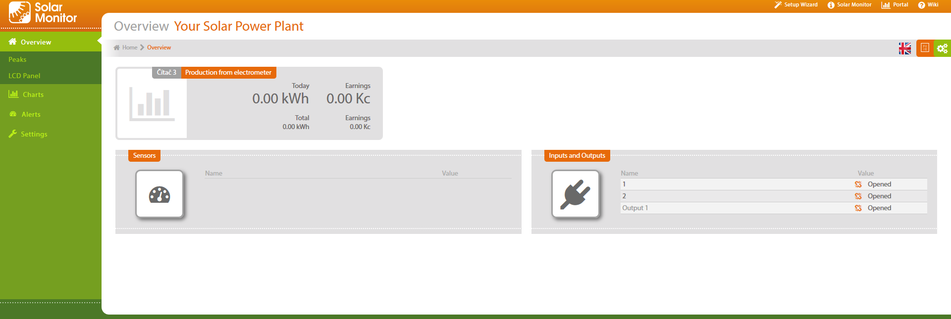
Overview gives you overall information about your PV plant.
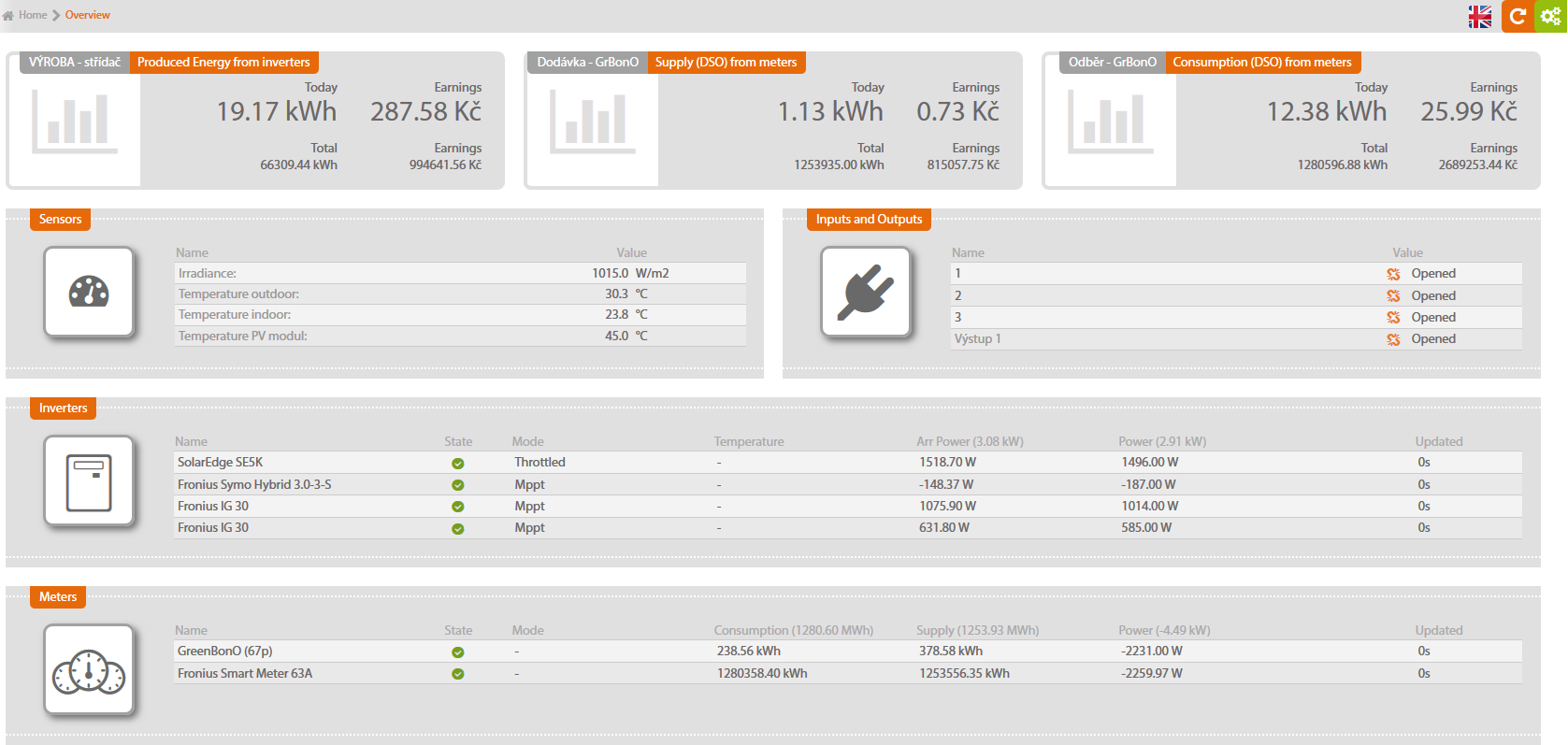
This menu shows all important information about your PV plant. If there is an alarm status of any component (it doesn't work properly or exceeds limit values) it is highlighted in colours.
Orange colour appears immediately after exceeding the limits. With sensors that send notification (e-mail, SMS) or record alarms in history, this status is considered an alarm after the “sensor alarm delay” runs out. Red colour appears, notification to the user is sent and/or it is recorded in alarm history.
Relevant sensor setup, time delays before alarm announcement and ways of notification to the user to be found in chapter Sensors and alarms.
These boxes show today's and total production in kWh and today's and total revenue in Czech crowns. Revenue is calculated roughly: multiply number of kWh produced by current Green Bonus price (or obligatory purchase). You have to set up the prices in menu Billing/Price setting, see chapter Inputs & Counters.
In order to show supply and consumption, a meter (e.g. GreenBonO) must be connected to Solar Monitor. Counting supply and consumption must be set up in the menu of Inputs and counters.
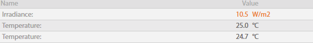
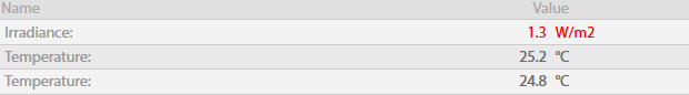
This box shows all detected sensors and their current values. The values are updated every second. You can name sensors and set up limit values in menu System setting/Sensors and alarms, see chapter Sensors and alarms.
It shows current status of two binary inputs and one relay output in Solar Monitor unit. Each input has two possible states: Opened or Closed. You can use these inputs to connect any component with contact status signaling - e.g. surge, movement sensor, door sensor, optical barrier or security output.
Inputs are able to distinguish 100 millisecond.
You will find Description of input connection and their set up in chapter Digital inputs and outputs.
With SM2-AD module, SM2-DI module connected, it shows current status of inputs and outputs of these modules.
All connected and correctly set up inverters, MPPT trackers, batteries, meters are shown here, including their status, current regime, output and temperature. These values come straight from the inverters every second.
Some manufacturers don't give all parameters (e.g. temperature).
Solar Monitor unit provides interactive graphs of counters.
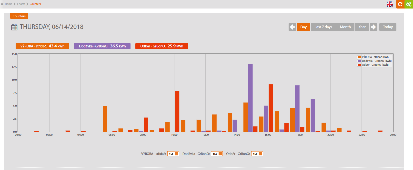
These graphs show values of each connected meters and power produced. There is automatic zoom function when you select particular meter. When you run a mouse on a bar, the value and time entry are shown.
Notice: if you need more detailed summary, ask for info on using our portal. See www.solarmonitor.cz
A bar chart of your PV plant production.
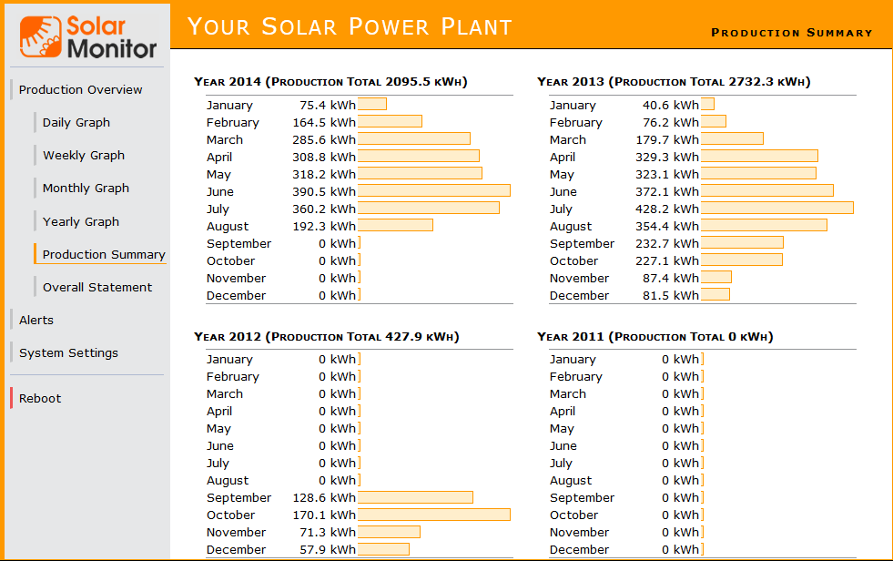
It shows power produced monthly in the last 4 years. It is a simple instrument for comparing production.
General Overview displays detailed data of your PV plant operation.
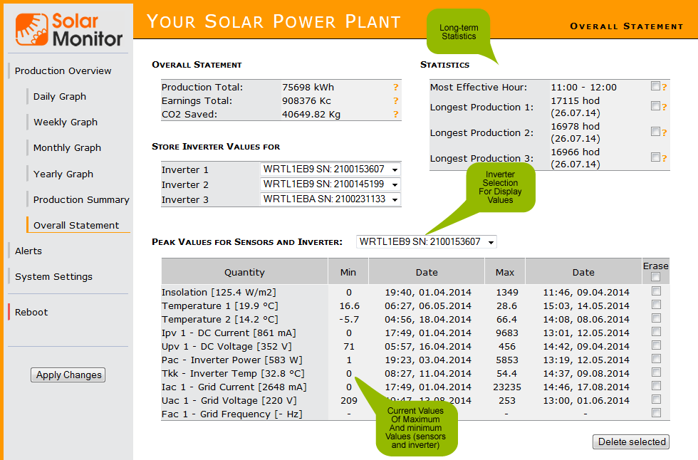
Total production, total revenue
It shows total production in kWh and Cz crowns. Financial figure is only roughly calculated, kWh multiplied by current Green Bonus purchase rate (or obligatory purchase rate). This figure doesn't take the rate changes into account.
Total amount of CO2 spared
It shows the number of CO2 in kg that would traditional production using fossil fuel produce compared to PV plant production of CO2.
Save the inverters values
Choose up to 3 inverters whose values you want to be downloaded and recorded in the table of record values.
The most efficient time:
It shows hour with the highest average production.
The longest production:
The longest production day of each inverter.
Table shows maximum and minimum values of sensors and inverter selected in sliding box at the top of the table. You can erase each line and start watching maximum and minimum values again.
Menu Alerts enables selecting the way of informing the user about alarms.

Table shows monitored components of a PV plant, their current status and limit values. It enables setting up the way of informing the user about alarms via e-mail or SMS. You can set up the limit values of sensors in the v menu “System set up\Sensors and alarms”, see chapter 4.1.3 Sensors & Alerts.
Sensors
If any sensor connected to the unit exceeds the limit values, a notification to the user is sent.
Sensors in default setting have 60 seconds delay, inverters 5 seconds delay. Further info on setting up the delay in chapter 4.1.3 Sensors and alarms.
Inputs
When input status (connected / disconnected) changes in a way not allowed by the user, a notification to the user is sent immediately.
Irradiation production check
If irradiation exceeds preset limit value and the inverter doesn't produce power, a notification is sent. Irradiation sensor is essential for this function.
Sending production report
A production report (selected type of message) is sent to the user in preset intervals.
If a failure is detected at the device (e.g. inverter), a notification to the user is sent immediately.
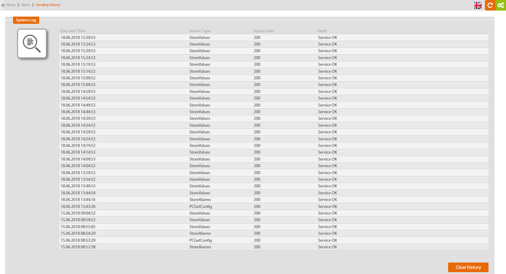
In the menu History of alarms you can find a record of events - log.

This chart records time when alarms started and ended in chronological sequence. You can erase the history with the button in the corner down on the right.
In default setting only alarms that caused a notification (e-mail or SMS) to the user are recorded. If alarm appears at the sensor without sending messages set up, this alarm will not be recorded in History of alarms.
If you don't want an e-mail or SMS notification sent, but you want to record alarms, tick a box “record alarms in history” on page System Settings / Sensors & Alerts.
This table shows each adjustment of active and reactive power production of a PV plant.

You can erase the history with a button in the right corner down.
Sent data to portal are logged here.
You can erase the history with a button in the right corner down.
Sent data to portal are logged here.
You can erase the history with a button in the right corner down.
Expansion modules add functions to the basic Solar Monitor unit.
In case you install SM2-MU without any other modules, skip this stage.
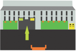
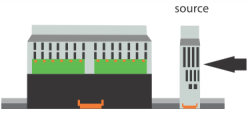
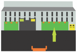
Connect HBUS to SM2-MU. Then connect all modules to the SM2-MU as in the picture bellow.
PC module (Power Control) controls your PV plant's power production. PV plant automatically adjusts its production according to purchaser's (ČEZ, E.ON, etc.) requirements. PC module can control both active and reactive power production.
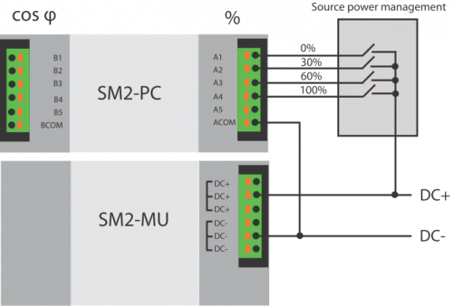
Power control signals wiring
Signal DC- has to be connected to ACOM and BCOM terminals in order to control the power. Signal DC+ has to be connected to the multiple terminal of power control source (net operator's device). Power control signals are connected to terminals A1-A5 to control active power in % and to terminals B1-B5 to control reactive power (cos φ). The following picture shows sample scheme of active power control wiring in 0 - 30 - 60 - 100%.
Start and configuration
As soon as the modules are connected and Solar Monitor unit is connected to the power supply, a green LED diode indicating status should glow. In case it doesn't glow, check if module is connected to SM2-MU. Open menu “System set up / Power control” in you browser. You have to set up inputs combinations and relevant power control values in % or cos φ here.
If you wish to use PC module for more Solar Monitor units, select option “Remote” in menu “Power control source” for each unit. Fill in the address of SM2-MU, where the power control module is connected. .

Connection

Configuration for 32 values of power control

| Binary inputs | 2 x 5 inputs with usual Vcc a GND |
|---|---|
| Terminals | max diameter 1,5 mm? |
| Connectivity | HBUS |
| Dimensions | 35.6 x 89.7 x 62.2 mm |
| Installation | DIN rail |
| Power supply | 12 – 24 V DC, max 100 mA |
| Degree of protection | IP20 |
| Temperature range | -25 °C to +60 °C |

AD module (Analog Digital) increases number of devices that can be connected to the Solar Monitor.
It measures current and voltage values at input devices and controls output devices according to the measured values.
It is possible to control other sensors at the inputs, switch on output relays, or set up analog output voltage values depending on unknown variable values available in the system. E.g. we can control accumulator's supply power depending on the PV plant's current production.
| Inputs | |
|---|---|
| 2x analog differential | 0 – 10 V, 0 - 20 mA |
| 1x analog | 0 – 10 V, 0 – 20 mA, 0 – 100 mV, 0 – 20 mV |
| Outputs | |
| 1x analog | 0 – 10 V |
| 2x relay | 48 V, 3 A |
| Connectivity | HBUS |
| Dimensions | 35,6 x 89,7 x 62,2 mm |
| Installation | DIN rail, wall |
| Power supply | 12 – 24 V DC, max 100 mA |
| Degree of protection | IP20 |
| Temperature range | -25 °C to +60 °C |
Module installation to be found here >>
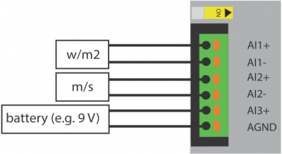
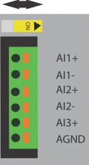
With analog inputs AI1 and AI2 the ranges of:
0 - 20 mA a 0 - 10 V are available for voltage or current measuring.
With analog input AI3 the ranges of:
0 - 20 mA, 0 - 10 V, 0 - 20mV, 0 - 100 mV are available for voltage or current measuring.
Measurement ranges are set up before module is delivered! Correct specification when you order SM2-AD module is essential. It is possible to connect pyranometer (measures solar irradiation), anemometer (measures wind speed) or battery.
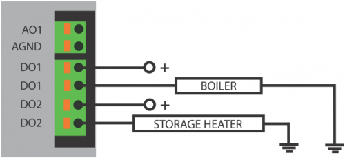
Analog output A0 to be connected in the same way. Voltage of 0-10V is detected at output terminals depending on current production or temperature. It can be used for continuous regulation of appliances, e.g. ventilation fan.
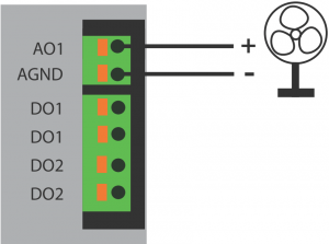
Digital (relay) outputs DO to be connected in the same way as with SM2-MU. E.g. to the boiler or storage heater as shown in the picture.
In case you don't intend to control voltage at your SM2-AD module's analog output, go to Next >>
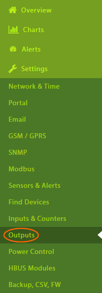
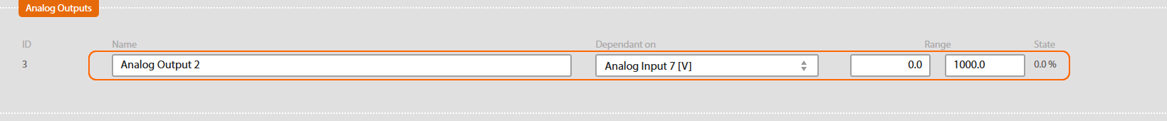
Open menu “System Setup / Outputs” in your web browser.
We set up analog output in the same way as digital outputs. Select the factor determining the output setup (e.g. temperature in the room with inverters, PV plant's production).
1st example: Regulation of Ventilation Revolving
Set up the temperature range corresponding to value 0 - 10 V at the output. The temperature is going to determine ventilation revolving.
I.e.:
y = the number of Volts in the range from 0 (V) to 10 (V) that output will deliver with a given temperature range
given temperature range: x1 = minimum (°C) to x2 = maximum (°C), e.g. 15 - 40 °C
x = current temperature in the room (°C), e.g. 28 °C
y = [10 / (x2 - x1)] * (x - x1)
y = [10 / (40 - 15)] * (28 - 15)
y = 5,2 V
2nd example: Charging Storage Battery
Set up PV plant's production range corresponding to the value 0 - 10 V at the output. This will determine charging the storage battery.
I.e.:
y = the number of Volts in the range from 0 (V) to 10 (V) that output will deliver with a given PV plant's production range
given PV plant's production range: x1 = minimum (W) to x2 = maximum (W), e.g. 2500 - 10000 W
x = current PV plant's production (W), e.g. 5200 W
y = [10 / (x2 - x1)] * (x - x1)
y = [10 / (10000 - 2500)] * (5200 - 2500)
y = 3,6 V
SM2-MU can operate up to 8 SM2-AD devices.
If there are two SM2-AD modules connected to one Solar Monitor unit, they must have two different addresses for communication with SM2-MU.
In order to do so, switch over yellow shifting switch. If there are more than two SM2-AD modules connected to SM2-MU, specify the number in your order. The shifting switch changes addresses 2-3, 4-5, 6-7, 8-9.
DI module increases the number of unit's digital inputs significantly and enables connecting other devices.
Module SM2-DI has 10 digital inputs. Digital inputs DI can be connected in the same way as inputs to SM2-MU. You can easily connect movement sensor, surge, optical barrier, door sensor and other devices that use contact output to indicate its status.
There are two ways of wiring.
The first one requires connecting terminal DC- to SM2-MU with relevant terminal DCOM at the module SM2-DI. One terminal DCOM goes with inputs DI1–DI5 and the second terminal with inputs DI6–DI10. In order to start the input, signal DC+ from SM2-MU unit has to be connected to relevant terminal of SM2-DI terminal.

For the second type of wiring, where inputs of SM2-DI module use external power supply (see the following picture), voltage has to be in the range of 8-80 V.

When you have connected the modules and Solar Monitor unit has been connected to the power supply, green LED diode indicating status should glow. If it doesn't glow, check the wiring of SM2-MU and the module.
Open menu “Settings / Inputs & Counters” in your browser.
Select limit values for relevant connected inputs.
It is possible to choose the type of message (e-mail, SMS) that informs the user of changes in input values.
| Binary inputs | 2 x 5 inputs with standard Vcc and GND |
|---|---|
| Terminals | max diameter 1.5 mm? |
| Connectivity | HBUS |
| Dimensions | 35.6 x 89.7 x 62.2 mm |
| Installation | DIN rail |
| Power supply | 12 – 24 V DC, max 100 mA |
| Degree of protection | IP20 |
| Temperature range | -25 °C to +60 °C |
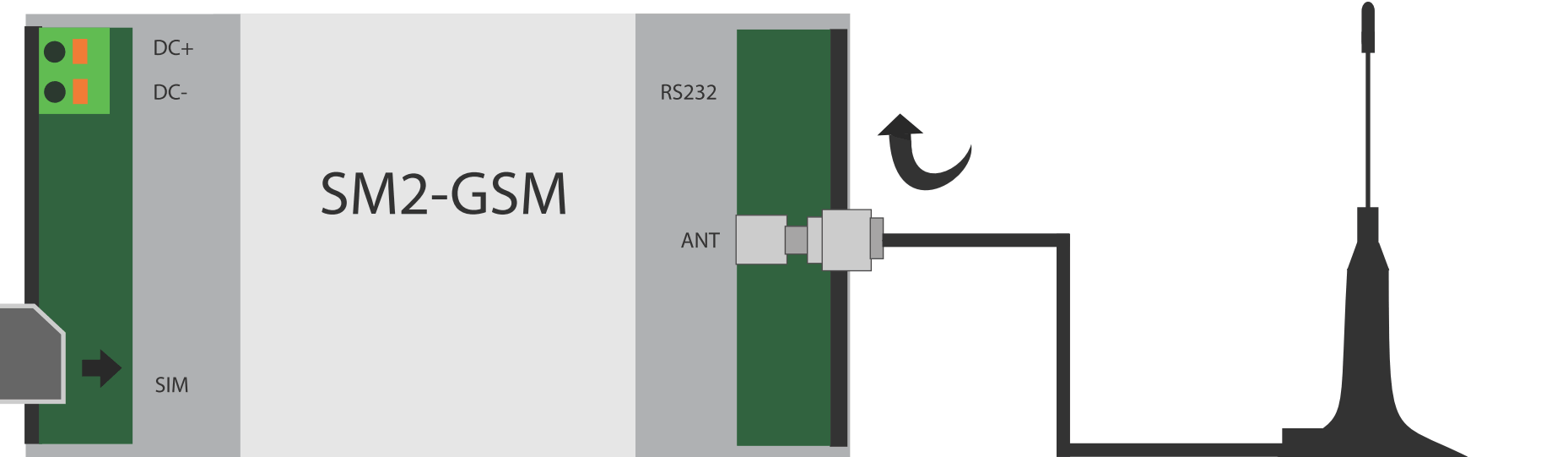
You can receive text messages informing you of your PV plant via GSM modem. This way you notice every outage and alarm. GSM modem enables GPRS communication too, or telephone calls. Functions of GSM modem can be used in other applications as well.
Connecting Aerial and Inserting SIM Card
Connect the aerial with SMA connector to the GSM modem. Then insert the SIM card as in the following picture. The SIM card mustn't have PIN code set up. You can deactivate PIN in a mobile.
Start and Configuration
When you have connected the modules and Solar Monitor unit has been connected to the power supply, green LED diode indicating status should glow. If it doesn't glow, check the wiring of SM2-MU and the module.
Open menu “System set up/ E-mail and SMS” in your browser. Tick GSM modem option box and enter phone numbers. Modem is activated in a few seconds and when it has been finished, you can send a trial SMS by clicking on button “Test SMS”..
You can find here how to configurate SM2-GSM.
| RF parameters | |
|---|---|
| Quad-band | 850/900/1800/1900MHz |
| GPRS Multi-slot Class | 12, 1~12 configurable |
| Compliant to GSM Phase 2/2+ | Class 4 |
| (2W @ 850/ 900 MHz) | |
| Class 1 | |
| (1W @ 1800/1900MHz) | |
| Certificates | CE, FCC, GCF, ICASA, PTCRB, TELCEL, IC, NCC, UCRF, Rogers, ANETEL |
| Aerial | |
| Connector | SMA (male) |
| Interface | |
| RS232 | HBUS (DIN rail, bottom pluggable, no external wires needed) and RJ12 connector1 |
| Max. distance | 12 m |
| Electrical parameters | |
| Power supply | 9-35 V DC, typ. 1 W @ 12V2, 3 |
| Mechanical parameters | |
| Dimensions | 53.6 x 89.7 x 62.2 mm |
| Mounting | DIN rail |
| Screw terminals | 0.5 mm² - 1.5 mm² cable cores |
| Degree of protection | IP20 |
| Operating temperature | -25 .. +60 °C |
| LED diodes | Status, GSM network |
1 … Interface connectors are mutually exclusive. The HBUS interface is intended to be used with the SM2-MU unit module. With the RJ12 connector the SM2-GSM module can be used as an individual GSM/GPRS modem with automatic power management by the DTR signal.
2 … There is no need for additional power supply if module is connected with the HBUS to the SM2-MU. In this case power supply for the SM2-MU should be calculated to provide sufficient power for all modules on the HBUS.
3 … During transmission there can be consumption peak bursts up to 6.4 W.

SM2-Bus Extension is the newest device of Solar Monitor expansion modules.
SM2-BE has 3 ways of use.

Connection SM2-BE with Studer Xcom-232i

The diagram of the entire system here.